Commissioning, Startup, Operation, and Shutdown
Model 3410 Installation, Operation, and Maintenance Manual
41
c) Stagger the joints in each ring by 90 degrees.
Make sure the center of the lantern ring lines up with the flush tap in the stuffing box.
Any extra rings are spares.
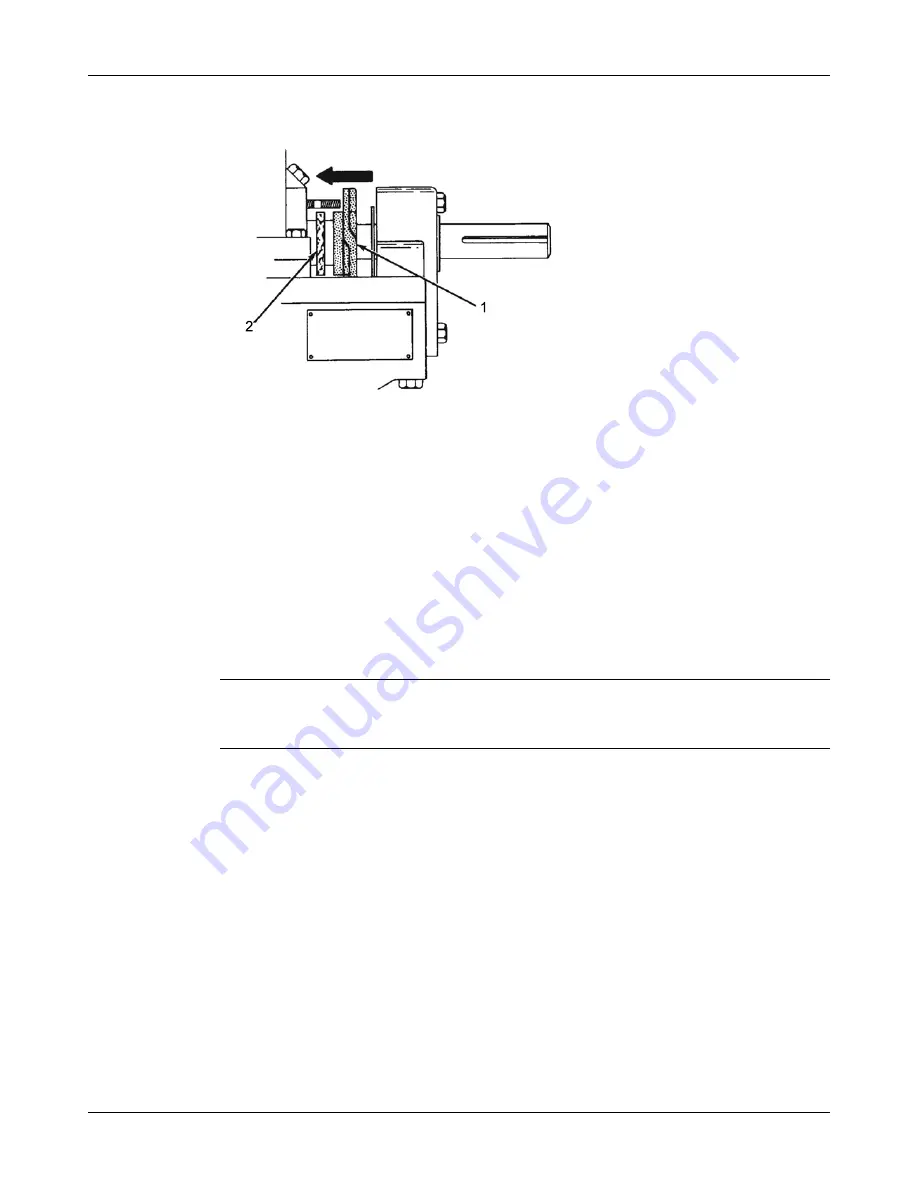
1. Gland
2. packing
6. Hand-tighten the gland nuts evenly but not tight.
7. To remove the packing from the stuffing box, do the following:
a) Remove the gland assembly.
b) Remove the packing with a packing hook.
c) Remove the lantern ring by inserting a wire hook into the ring on the outer edge.
d) Clean the stuffing box.
An alternate method of removing the packing is to remove the upper-half casing (see the
Maintenance chapter). Remove the packing and lantern ring, and then inspect the sleeves
or the shaft. Replace the sleeves or the shaft if either is deeply grooved.
Mechanical seal options
NOTICE:
Mechanical seals used in an ATEX classified environment must be properly certified. Failure to
ensure this may result in equipment damage or physical injury.
When mechanical seals are furnished, the description and identification are indicated on the
order forms. Installation drawings from the seal manufacturer are attached to pump. Most seals
are installed and adjusted at the factory. File these drawings for future use in maintenance and
adjustment of the seal whenever the pump is disassembled.
Prepare the seal for operation
To properly prepare the seal for operation, various cooling and flushing flows may have to be
connected. In some cases, these flows are recirculated from pump casing. In other cases,
liquid from an outside source may be used. Connect cooling and flushing flows to the seal as
directed in instructions supplied by the manufacturer.
All Model 3410 mechanical seals use O-ring mounted stationary seats and a flush gland with a
pilot fit in the ID of the stuffing box as standard. All S group pumps are standard without shaft
sleeves; sleeves are optional. M, L, and XL groups are standard with shaft sleeves and sleeve
nuts.


