Documentation HG G-73650ZD | English, Revision 05 | Date: 09.03.2017 | www.goetting-agv.com
101
Chapter 5: Commissioning
5.8.3 Optimising the steering controller
The aim of the steering servo is to set the steering angle as quickly and exactly as possible.
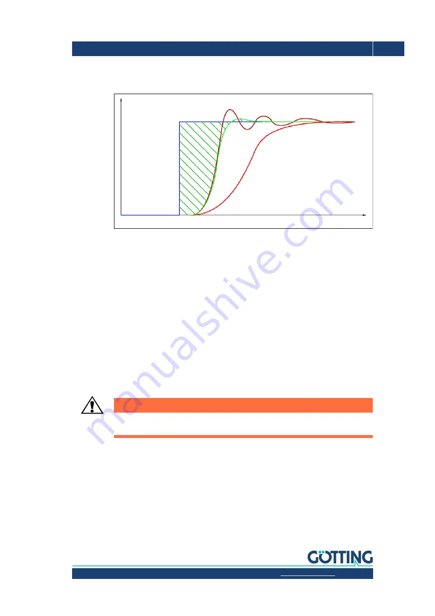
Figure 78
Characteristics of differently adj. steering controllers over time
The graphic shows a steering angle jump (blue curve).
The dark red curve represents a steering controller that tends to oscillate.
The bright red curve represents a very slow steering controller.
The green curve represents a well adjusted steering controller.
The optimum is when the shaded area between the target and actual angle is as small as
possible. This area corresponds to the approximate proportional lateral error the vehicle will
have on driving the curve.
As can be seen in the diagram, a considerable portion of the area arises due to the dead time
from the jump of the target elbow to the first reaction of the steering. This time arises due
to the necessary communication of the individual components, activation times of valves
etc. This is why it is necessary to optimise here.
Fast communication across a few con-
trol systems is the best.
Valves that are as fast as possible and/or strong and fast steering
servos should also be fitted.
ATTENTION!
The maximum speed of the vehicle, particularly in curves, depends on the speed and re-
sponse time of the steering.
The target steering angles should also be set as precisely as possible. For example, if a dead
band of one degree is permitted, the vehicle will oscillate around the target line. That hap-
pens because the vehicle moves so far from the target track until the target steering angle
exceeds the dead band. Only then does a correction take place. The vehicle runs over the
target line and, on the other hand, the vehicle only reacts if the deviation of the vehicle has
become so large that the target steering angle breaks through the dead band.
Steering angle
Time


