background image

First Time Setup

HG 76342-A

English, Revision 01, Date: 27.01.2014

10

NOTE!

You have to observe:

-

The connected PC should have a fixed IP address. (no DHCP)

-

The LAN-Interface at the PC must be detected as connected. Check the parame-
ter of the LAN-Interface with the „ipconfig“-command.

-

If the LAN-Interface of the PC is correctly recognized then press the „refresh“-but-
ton of the UCP-config-program.

-

An active firewall could prevent the communication to the radio modem.

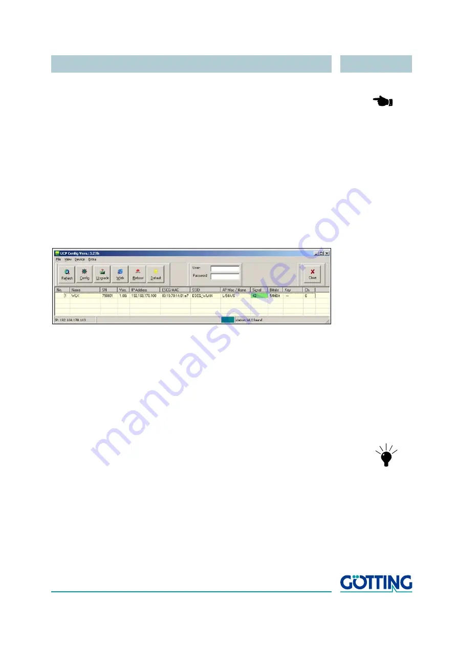
After the start the UCP-Config-Program ascertained all network interfaces that are ac-
tive at the PC. After this the UCP-Config-Program sends broadcast UDP requests to all 
these interfaces. The registered answers of the HG 76342-A devices are shown in a 
list.

Figure 8

Screenshot UCP-Config program

All located HG 76342-A devices are shown in a list with their station names, firmware 
versions and addresses. The WLAN connection is also shown with a signal quality val-
ue. The value can be interpreted as follows:

-

Signal 

 40 

  very good connection

-

Signal 

 30 

 good connection

-

Signal 

 20

  connection is OK, the device starts to search for better AP’s

-

Signal < 20 

  connection restricted, the bit rates will be lowered

NOTE!

For a more detailed description of the UCP config program 
please refer to the separately available manual.

2.3

Reset to factory default

The factory default settings can be restored by pressing the reset button located on 
the front panel for a period of more than 10 Seconds. While the reset button is pressed, 
the “ON”-LED blinks orange more faster. When the radio modem does a restart the de-
fault settings are configured. Now the reset button can be released.

Summary of Contents for HG 76342-A

Page 1: ...g Top Hat Rail or Flange Casing HG 76342 A English Revision 01 Dev by C M Date 27 01 2014 Author s RAD G tting KG Celler Str 5 D 31275 Lehrte R ddensen Germany Tel 49 0 51 36 80 96 0 Fax 49 0 51 36 80...

Page 2: ...1 2 HG 76342ZA with Flange Casing 9 2 2 The UCP Config Program 9 2 3 Reset to factory default 10 3 WEB Interface 12 3 1 Info Page 12 3 1 1 Bridge Information 13 3 1 2 IP Info 13 3 1 3 WLAN Info 14 3 1...

Page 3: ...a a serial port This data can be exchanged via a TCP or UDP Socket with other devices by using the LAN or WLAN interfaces of the radio modem The HG 76342 A needs many parameters to handle all the diff...

Page 4: ...250MHz RS 232 opt RS485 RS422 2 Port Switch MINI PCI MINI PCI RF Hardware 802 11 a b g 2Mbyte serial Flash 16 Mbyte DDR RAM Watchdog TxD RxD DTR 3 2 7 8 4 6 DSR RTS CTS SER1 1 9 DCD RI 5 RJ45 or M12 T...

Page 5: ...ble polarity and automatically connects the right signal lines The serial port is connected via a 9 pin female D SUB connector The pin allocation makes it possible to connect to a computer COM port wi...

Page 6: ...4 2 5 pin M12 female Power Figure 4 Pin allocation 5 pin M12 female Power Pin RS 232 RS 422 485 Function Direction Function Direction 1 DCD IN NC 2 TxD OUT Tx OUT 3 RxD IN Rx IN 4 DSR IN NC 5 GND GND...

Page 7: ...ation HG 76342 A ready for service Serial steady off no communication partner is connected to the radio modem green A communication partner is connected to the radio modem When data is transmitted or...

Page 8: ...onnection The Port 1 or 2 LED on the front panel shines green when a connection has been established via the Ethernet The WLAN LED on the front panel will be blinking red because usually no suitable W...

Page 9: ...ure 6 Dimensions HG 76342YA with flange casing 2 2 The UCP Config Program To do the first time setup the radio modem has to be connected via the LAN Interface to the computer PC that runs the UCP Conf...

Page 10: ...a list Figure 8 Screenshot UCP Config program All located HG 76342 A devices are shown in a list with their station names firmware versions and addresses The WLAN connection is also shown with a signa...

Page 11: ...2014 11 Main factory default values Device Name HG76342 SSID ESCG_WLAN WEP OFF WPA OFF 802 1x OFF 802 1x user empty 802 1x password empty MODE 802 11b g IP 192 168 170 100 Netmask 255 255 255 0 Gatew...

Page 12: ...low This page and the page listing all currently registered access points can be opened freely In case that a User and Password have been defined accessing all other web pages requires that those val...

Page 13: ...he daytime is used for sys log messages Bridge Name This name is configured at the Admin page The name is shown in the config program in the first column MAC Address This is the MAC address that the d...

Page 14: ...etwork Phy mode The following modes are supported 802 11 bg 2 4 GHz Band with 11 or 54 MBit max 802 11 g 2 4 GHz with 54 MBit max 802 11 b 2 4 GHz with 11 MBit max 802 11 a 5 GHz with 54 MBit max SSID...

Page 15: ...an cycles are shown here Info Note Port 1 2 Down no LAN cable is connected or the LAN Client is not switched on Up LAN cable is connected client detected 10 oder 100 MBit transmission speed full oder...

Page 16: ...input signals for the device RTS DTR are output signals Green letters marks active signals Black letters marks inactive signals Table 8 Info Page Serial Info Info Note Relay Configuration and status...

Page 17: ...If a USB memory is detected debug information will be stored in a file on the USB memory stick If an USB printer is connected to the radio modem USB Port the following status is shown Printer URI is...

Page 18: ...qualified to drive RF Cards the Chipsets from Atheros AR5112 AR5113 AR5414 Relay Relay switch contact can be switch via WLAN or LAN AUX Input optional Signal input 24V galv separated Antenna connecto...

Page 19: ...b 11 5 5 2 1 MBit s 802 11g 54 48 36 24 18 12 9 6 MBit s 802 11a 54 48 36 24 18 12 9 6 MBit s Frequencies ISM Band 2 400 MHz to 2 483 MHz U NII Band 5 150 MHz to 5 350 MHz ETSI RegTP Indoor 5 470 MHz...

Page 20: ...ectors and LEDs 5 Figure 4 Pin allocation 5 pin M12 female Power 6 Figure 5 Dimensions HG 76342YA with Top Hat Rail Casing 8 Figure 6 Dimensions HG 76342YA with flange casing 9 Figure 7 Sketch Arrange...

Page 21: ...o 13 Table 6 Info Page WLAN Info 14 Table 5 Quality of the reception signal 15 Table 7 Info Page LAN Info 15 Table 9 Operation Mode of the Relay 16 Table 8 Info Page Serial Info 16 Table 10 Info Page...

Page 22: ...ion each documents includes a list of contents showing the page numbers following the front If a document exceeds 10 pages it also has a drawings list and a list of tables on the last few pages If req...

Page 23: ...e used according to the description This instruction manual has been drawn up to the best of our knowledge Installation setup and operation of the device will be on the customer s own risk Liability f...

Reviews: