Commissioning
English, Revision 06, Date: 12.07.2011
11
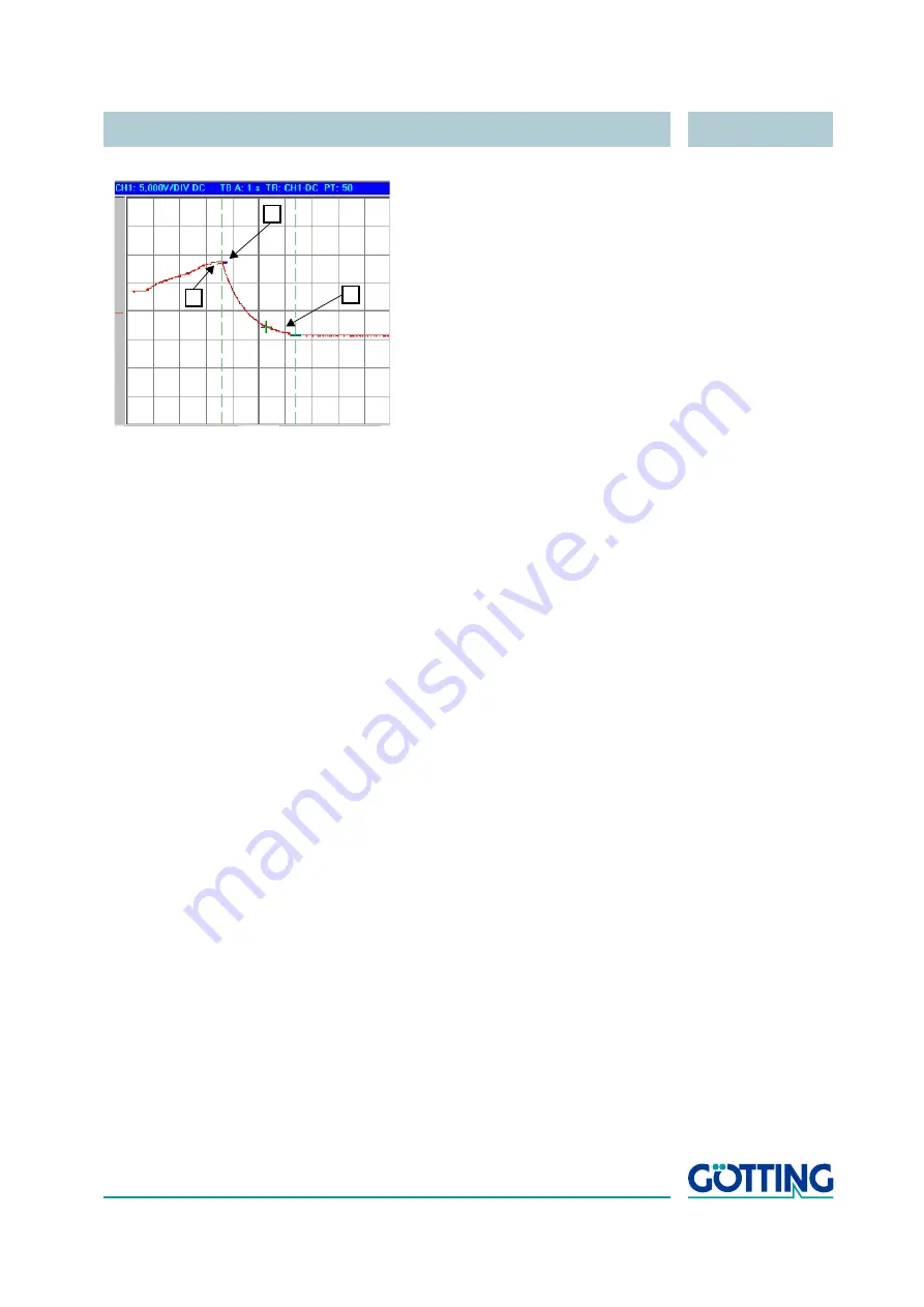
Figure 4
Function of the Jump Filter
A jump of more than one track width is detected at position 1. 400 ms later, at position
2, the reaction time is over and the output signal approaches the new value until, after
approx. 2,8 sec, the new output value is reached at position 3. The filter settings for
this example are:
Bridge a track Jump
= 20 and
Jump Increment
= 50. These
two filters are only available for the analog output signal in PLC mode (refer to
Menu
Output-Input Settings
Once all settings have been entered, it is necessary to save the new parameters (refer
to section 4 on page 19).
2.5
Improving the resolution
If the values for track width and camera height (see 4.3 on page 24) are adjusted cor-
rectly the resolution of the system is 1mm. The resolution can be improved by applying
the following trick:
Example:
installation height: 100 mm, track width: 25 mm
•
Enter 200 mm as installation height and 50 mm for the track width, then the resolu-
tion will be 0.5 mm
•
when entering 400 mm as installation height and 100mm as the track width, the
resolution increases to 0.25 mm
Therefore the thresholds for the deviation warning have to be altered correspondingly
if required (see 4.4 on page 26).
2.6
Design of the barcode
2.6.1
Structure of the 2/5 interleaved barcode
The interleaved barcode is numeric code which can present the figures from 0 to 9.
The code is made up of two bold and three narrow lines or according to this two bold
and three narrow spaces. The first figure is made up of five lines, the second consists
of the spaces which follow the aforementioned lines.
First of all, there is a start code which consists of a narrow line and a narrow space
followed by another narrow line.
1
2
3


