background image

80 SERIES

OM-06790

MAINTENANCE & REPAIR

PAGE E - 8

finished faces; even fingerprints on the faces can
shorten seal life. If necessary, clean the faces with a
non‐oil based solvent and a clean, lint‐free tissue.
Wipe 

lightly

 in a concentric pattern to avoid

scratching the faces.

Inspect the seal components for wear, scoring,
grooves, and other damage that might cause leak­
age. If any components are worn, replace the com­
plete seal; 

never mix old and new seal parts

.

If a replacement seal is being used, remove it from
the container and inspect the precision finished
faces to ensure that they are free of any foreign
matter.

To ease installation of the seal, lubricate the bel­
lows and O‐rings with water or a very 

small

amount of light lubricating oil, and apply a drop of
light lubricating oil on the finished faces. Assemble
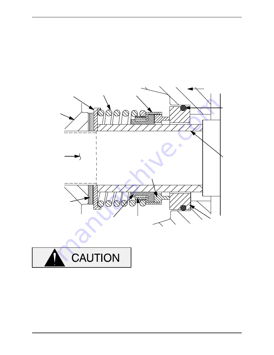
the seal as follows, (see Figure 3).

INTERMEDIATE

O‐RING

ENGINE

STATIONARY

ELEMENT

ROTATING

BELLOWS

IMPELLER
SHIMS

IMPELLER

SPRING

RETAINER

ELEMENT

CRANKSHAFT

SEAL

SLEEVE

SPRING CENTERING

WASHER

DRIVE BAND

Figure 3.  Seal Assembly

This seal is not designed for operation at
temperatures above 160

_

F (71

_

C). How­

ever most petroleum products such as
gasoline are more efficiently handled at
ambient temperatures. Do not use at high­
er operating temperatures.

If the intermediate was removed, lay it on a flat sur­
face with the impeller side facing up.

Subassemble the O‐ring onto the stationary seat
and press this subassembly into the intermediate
bore until it seats squarely against the shoulder.
Slide the assembled intermediate and stationary
seat over the shaft and secure the intermediate to
the engine with the hardware (9 and 10). When in­
stalling the intermediate, use caution not to dam­
age the stationary seat on the shaft threads.

NOTE

If the intermediate was not separated from the en­
gine during disassembly, subassemble the O‐ring
into the stationary seat and use a piece of plastic
pipe to press the seat into the intermediate bore un­

Summary of Contents for 82D1-1B20 FT4-X

Page 1: ...OM 06790 01 October 7 2015 GORMAN RUPP PUMPS www grpumps com e2015 Gorman Rupp Pumps Printed in U S A INSTALLATION OPERATION AND MAINTENANCE MANUAL WITH PARTS LIST 80 SERIES PUMP MODEL 82D1 1B20 FT4 X...

Page 2: ...NUMBER Please record your pump model and serial number in the spaces provided below Your Gorman Rupp distributor needs this information when you require parts or service Pump Model Serial Number The...

Page 3: ...tion Lines In Sumps PAGE B 3 Suction Line Positioning PAGE B 4 DISCHARGE LINES PAGE B 4 Siphoning PAGE B 4 Valves PAGE B 4 Bypass Lines PAGE B 5 GROUNDING PAGE B 5 OPERATION SECTION C PAGE C 1 PRIMING...

Page 4: ...oval PAGE E 6 Impeller Removal PAGE E 7 Seal Removal and Disassembly PAGE E 7 Seal Reassembly and Installation PAGE E 7 Impeller Installation And Adjustment PAGE E 8 Pump Casing Installation PAGE E 9...

Page 5: ...O Box 1217 Mansfield Ohio 44901 1217 Phone 419 755 1011 or Gorman Rupp of Canada Limited 70 Burwell Road St Thomas Ontario N5P 3R7 Phone 519 631 2870 For information or technical assistance on the po...

Page 6: ...d non flam mable atmosphere free of combustible hazards It cannot be further modified without affecting performance and safe ty factors The shield and spark arrest ing modifications must be inspected...

Page 7: ...ternal combustion engine in an explosive atmosphere When operating internal combustion engines in an enclosed area make cer tain that exhaust fumes are piped to the outside These fumes contain carbon...

Page 8: ...application Since the pressure supplied to the pump is critical to performance and safety be sure to limit the incoming pressure to 50 of the maximum permissible operating pressure as shown on the pum...

Page 9: ...s close as practical to the liquid being pumped Level mount ing is essential for proper operation The pump may have to be supported or shimmed to provide for level operation or to eliminate vibra tion...

Page 10: ...is not furnished with the pump but is installed by the pump user make certain that the total area of the openings in the strainer is at least three or four times the cross section of the suction line...

Page 11: ...sired in the discharge line use a valve as large as the largest pipe to minimize friction losses Never install a throttling valve in a suction line A check valve in the discharge line is normally rec...

Page 12: ...by the liquid be ing pumped the unit must be grounded by attach ing the ground wire assembly to a ground rod In stall the ground rod in accordance with the Nation al Electrical Codes and all local co...

Page 13: ...ot prime when dry Extended operation of a dry pump will destroy the seal assembly Add liquid to the pump casing when 1 The pump is being put into service for the first time 2 The pump has not been use...

Page 14: ...ressure within the pump can cause parts being disen gaged to be ejected with great force al low the pump to cool before servicing Strainer Check If a suction strainer has been shipped with the pump or...

Page 15: ...ion In below freezing conditions drain the pump to prevent damage from freezing Also clean out any solids by flushing with a hose Operate the pump for approximately one minute this will remove any rem...

Page 16: ...quid to casing See PRIMING Suction check valve contaminated or damaged Clean or replace check valve Product vapor pressure too high Cool pump and product suction line Pump speed too slow Check engine...

Page 17: ...rdware Pump or drive not securely mounted Locate and eliminate source of air bubble Pumping entrained air Strainer clogged Check strainer and clean if neces sary Pump speed too high Check driver outpu...

Page 18: ...ly the same duty cycle the part can be checked and replaced before failure occurs reducing unscheduled down time For new applications a first inspection of wearing parts at 250 hours will give insight...

Page 19: ...n lift Since pump installations are seldom identi cal your performance may be different due to such factors as viscosity specific gravity elevation tem perature and impeller trim If your pump serial n...

Page 20: ...80 SERIES OM 06790 MAINTENANCE REPAIR PAGE E 2 PARTSPAGE ILLUSTRATION Figure 1 Pump Model 82D1 1B20 FT4 X...

Page 21: ...20 1 7 SPARK ARRESTER 29334 196 1 8 GUARD 34851 579 15120 1 9 RUBBER FOOT MOUNTING KIT 48152 607 1 10 HEX HD CAPSCREW B0504 15991 2 11 FLANGED HEX NUT 21765 312 4 12 CAUTION PLATE 38816 146 13990 1 13...

Page 22: ...80 SERIES OM 06790 MAINTENANCE REPAIR PAGE E 4 ILLUSTRATION Figure 2 Pump Parts Only 82D1 1B20 X PPO...

Page 23: ...A 17090 1 13 IMPELLER 2912F 13040 1 14 CASING GASKET SET 504G 18000 1 15 WEAR PLATE ASSY 2643A 15990 1 16 STUD C0606 15991 8 17 NAME PLATE 38812 041 13990 1 18 DRIVE SCREW BM 04 03 17000 4 19 CASING D...

Page 24: ...engine used in this pump is not standard It has been modified for use in handling gasoline and other petroleum products in a well ventilated non flam mable atmosphere free of combustible hazards It c...

Page 25: ...spring centering washer 11 and seal spring Slide the shaft sleeve 8 and rotat ing portion of the seal off the engine shaft as a unit Apply oil to the shaft sleeve and work it up under the rubber bello...

Page 26: ...STATIONARY ELEMENT ROTATING BELLOWS IMPELLER SHIMS IMPELLER SPRING RETAINER ELEMENT CRANKSHAFT SEAL SLEEVE SPRING CENTERING WASHER DRIVE BAND Figure 3 Seal Assembly This seal is not designed for opera...

Page 27: ...learance of 008 to 015 inch 0 20 to 0 38 mm between the impeller and the wear plate is also rec ommended for maximum pump efficiency This clearance can be obtained by adding or removing gaskets in the...

Page 28: ...GINE MODIFICATIONS The engine used on this pump is not a standard commercial model It has been specially modified by Gorman Rupp for pumping gasoline and other petroleum products in a well ventilated...

Page 29: ...For Warranty Information Please Visit www grpumps com warranty or call U S 419 755 1280 Canada 519 631 2870 International 1 419 755 1352 GORMAN RUPP PUMPS...

Reviews: