OM-07207
SUPER T SERIES
MAINTENANCE & REPAIR
PAGE E - 13
It is not necessary to remove the outer ring of the
coupling from the engine flywheel unless the cou
pling must be replaced. To remove the ring, disen
gage the hardware (4 and 5) securing it to the fly
wheel.
Remove any leveling shims used under the casing
mounting feet. Tie and tag the shims for ease of
reassembly.
Move the pump end to a clean, well equipped shop
area for further disassembly.
Loosening Impeller
(Figure 4)
Before attempting to loosen the impeller, remove
the seal cavity drain plug (25) and drain the lubri
cant. This will prevent the oil from escaping as the
impeller is removed. Clean and reinstall the drain
plug.
With the pump end separated from the engine and
the back cover (20, Figure 3) removed, wedge a
block of wood between the vanes of the impeller
and the pump casing to prevent rotation.
If removed, install the shaft key (17) in the shaft
keyway. Install a lathe dog on the drive end of the
shaft (15) with the “V” notch positioned over the
shaft key.
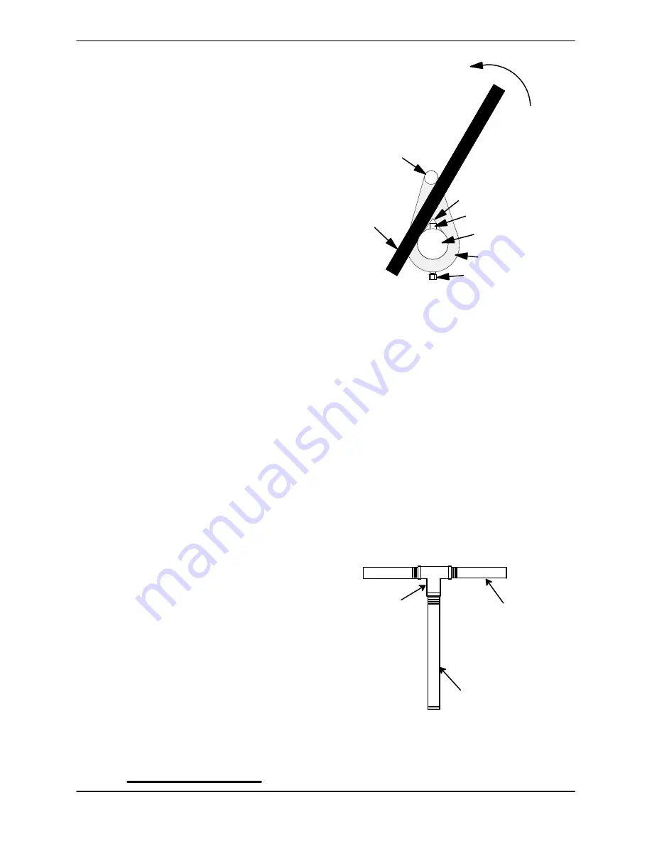
With the impeller rotation still blocked, see Figure 6
and use a long piece of heavy bar stock to pry
against the arm of the lathe dog in a counterclock
wise direction (when facing the drive end of the
shaft).
Use caution
not to damage the shaft or key
way. When the impeller breaks loose, remove the
lathe dog, key and wood block.
NOTE
Do not remove the impeller until the rotating assem
bly has been removed from the pump casing.
Turn
Counterclockwise
Lathe Dog Arm
“V” Notch
Shaft Key
Impeller
Shaft
Lathe Dog
Setscrew
Heavy
Bar Stock
Figure 6. Loosening Impeller
Rotating Assembly Removal
(Figure 4)
Remove the hardware (11 and 12, Figure 3) secur
ing the rotating assembly to the pump casing. Sep
arate the rotating assembly by pulling straight
away from the pump casing. Tie and tag the rotat
ing assembly shims (13) for ease of reassembly.
NOTE
An optional disassembly tool is available from the
factory. If the tool is used, follow the instructions
packed with it. A similar tool may be assembled us
ing 1/2‐inch pipe (schedule 80 steel or malleable
iron) and a standard tee (see Figure 7). All threads
are 1/2‐inch NPT.
Do not pre‐assemble the tool.
TEE
APPROX. 6 IN.
(152 MM) LONG
APPROX. 14 IN.
(356 MM) LONG
Figure 7. Rotating Assembly Tool
To install the tool, remove the vented plug (9, Figure
4) from the bearing housing, and screw the longest


