background image

OM−05229

JSV3H

PAGE E − 2

MAINTENANCE AND REPAIR

PARTS PAGE

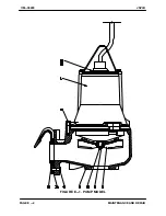
FIGURE E−1.  PUMP MODEL

Summary of Contents for JSV3H60-E5 230/1

Page 1: ... THE GORMAN RUPP COMPANY MANSFIELD OHIO GORMAN RUPP OF CANADA LIMITED ST THOMAS ONTARIO CANADA Printed in U S A Copyright by the Gorman Rupp Company INSTALLATION OPERATION AND MAINTENANCE MANUAL WITH PARTS LIST SUBMERSIBLE PUMPS MODEL JSV3H60 E5 230 1 ...

Page 2: ...ntification PAGE B 3 Wiring Diagram and Control Box Connections PAGE B 3 Liquid Level Devices PAGE B 5 OPERATION SECTION C PAGE C 1 PERFORMANCE CURVE PAGE C 1 CONTROLS PAGE C 2 PUMP OPERATION PAGE C 2 Liquid Temperature and Overheating PAGE C 2 Impeller Rotation PAGE C 2 STARTING STOPPING AND OPERATIONAL CHECKS PAGE C 3 Starting PAGE C 3 Stopping PAGE C 3 Operational Checks PAGE C 3 Cold Weather P...

Page 3: ... 8 Removing Bearings PAGE E 8 INSPECTION AND CLEANING PAGE E 8 Bearings PAGE E 8 Other Reusable Parts Except Seal Assemblies PAGE E 8 Cleaning Seal Assembly PAGE E 9 PUMP AND MOTOR REASSEMBLY PAGE E 9 MOTOR REASSEMBLY PAGE E 9 Installing Bearings PAGE E 9 Installing Shaft and Rotor Assembly PAGE E 10 Installing Motor Cover PAGE E 10 PUMP END REASSEMBLY PAGE E 11 Installing Seal Assembly PAGE E 11 ...

Page 4: ...ully or partially submerged mounted on guide rails installed in a wet well and to handle raw un screened sewage and effluents Installation of the guide rail system and other wet well hardware is not covered in this manual Refer to other literature accompanying the pump If there are any questions regarding the pump or motor which are not covered in this manual or in other literature accompanying th...

Page 5: ...trical power used to operate this pump is high enough to cause inju ry or death Obtain the services of a qu alified electrician to make all electrical connections This pump is wired at the factory only for the voltage shown on the nameplate Do not attempt to run the pump on alternate voltage Otherwise damage to the pump and injury or death to personnel can result Do not connect the pump motor dire...

Page 6: ... personnel If this pump is used to handle sewage take necessary precautions during maintenance and repair to prevent per sonal contamination which could result in illness The following precautions should be taken before attempting to open or ser vice the pump otherwise injury or death could result 1 Lock out the power to the control pan el to ensure that the pump will remain inoperative 2 Allow th...

Page 7: ...age and Hertz indicated on the motor name plate match the ratings on the control box e Carefully read all tags decals and markings on the pump assembly and perform all duties indicated f Check for any oil leaks If there is any indica tion of an oil leak see LUBRICATION in MAINTENANCE AND REPAIR SECTION E LUBRICATION These pumps are equipped with a mechanical double seal The lower seal prevents the...

Page 8: ...age the guide shoe at the top of the guide rails and lower the pump into the sump When the pump and guide shoe engages the discharge el bow baseplate it will form an automatic seal Reel in any slack control cable so that it is not dragged into the pump suction Piping NOTE Refer to PERFORMANCE CURVES in OPERA TION SECTION Cwhen determining the most ef ficient piping installation No suction piping i...

Page 9: ...tory If the conductors are shortened in the field resulting in loss of identi fication markers they can still be identified by their location relative to the ground wire Refer to FIGURE B 1 as seen from the free end of the cable the conductor immediately adjacent to and clockwise from ground green yellow is as signed number T1 The second clockwise conduc tor is T2 etc The conductors labeled P1 and...

Page 10: ...OM 05229 JSV3H PAGE B 4 INSTALLATION FIGURE B 1 INTERNAL MOTOR WIRING ...

Page 11: ...ith changes in liquid level thus activating an enclosed miniature switch S Bulb Float Type a bulb raises or lowers floats with the liquid level thus activating an enclosed miniature switch Other types of liquid level devices may also be used Consult the factory for the liquid level device best suited for your application Liquid level devices must be positioned far enough to allow 6 minutes between...

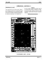
Page 12: ...evel The performance of your pump may be differ ent due to such factors as viscosity specific grav ity elevation temperature and impeller trim NOTE The curves apply to standard production models If your pump serial number is followed by an N your pump is not a standard production model Contact the Gorman Rupp Company to verify per formance PERFORMANCE CURVE JSV3H60 ...

Page 13: ...structions in this manual before restarting the pump Overheating can occur if the control box fails to provide overload or thermal protection or if the pump is operated against a closed discharge valve for an extended period of time The submersible motor is cooled by the liquid be ing pumped To minimize the chance of over heat ing when installed in a simplex application it is recommended that at l...

Page 14: ...To avoid the hazards of an unexpected motor start up do not at tempt to handle or service the pump un less all power to the motor has been shut off at the control box otherwise serious personal injury could result During motor shutoff by the thermal overload device control box circuits re main live Do not attempt to service any control box components unless in com ing power has been shut off After...

Page 15: ...uid If the casing is not sub merged or if the liquid begins to freeze remove the pump from the wet well and dry it thoroughly Run the pump for two or three minutes to dry the inner walls If the pump does freeze while it is out of the liquid submerge it until thawed if the liquid is near freez ing the pump must be submerged for an extended period of time Check thawing by starting the pump and check...

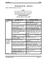
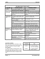
Page 16: ...G DEVICES TRIPPED CHECK CONTROL BOX CHECK FOR LEAKING SHAFT SEALS CUT O RINGS OR MOISTURE WICKING THROUGH OR CABLE CHECK CONTINUITY PER ELECTRICAL TESTING MOTOR OVERHEATED THERMAL SWITCHES TRIPPED ALLOW MOTOR TO COOL VOLTAGE TOO LOW OR TOO HIGH CHECK INCOMING VOLTAGE CHECK WIRING SIZE TYPE AND LENGTH SEE INSTALLATION SECTION B EXCESSIVE VOLTAGE DROP BE TWEEN PUMP AND CONTROL BOX MOTOR RUNS BUT DOE...

Page 17: ...FF EXCESSIVE NOISE OR VIBRA TION IMPELLER CLOGGED CLEAR BLOCKAGE IMPELLER LOOSE OR DAMAGED CHECK IMPELLER REPLACE IF NECESSARY MOTOR SHAFT OR BEARINGS REPLACE DEFECTIVE PUMPING ENTRAINED AIR CHECK WET WELL LIQUID LEVEL PUMP OPERATING OUTSIDE DE SIGNED OPERATING RANGE CHECK DISCHARGE HEAD AND FLOW ADJUST AS REQUIRED TO MEET PER FORMANCE SPECIFICATIONS CONT IMPELLER WORN OR DAMAGED REPLACE LIQUID BE...

Page 18: ...asured Normal amperage values are listed in Table 1 Section B these values apply only when the voltage at the site is the normal voltage listed Motor and Power Cable Continuity Set the megohmmeter at R x 1 scale and zero balance it Test as follows a Shut off incoming power to the control box and disconnect the motor power cable leads Connect the megohmmeter test leads to any two power cable leads ...

Page 19: ...ERATING EFFICIENCY PUMP MODELS THE FOLLOWING PUMP MODELS FROM SERIAL NO 1011595 UP ARE COVERED IN THIS SECTION JSV3H60 E5 230 1 IF YOUR PUMP SERIAL NUMBER IS FOLLOWED BY AN N YOUR PUMP IS NOT A STANDARD PRODUCTION MODEL CONTACT THE GORMAN RUPP COMPANY TO VERIFY PART NUMBERS PERFORMANCE CURVES FOR THESE PUMPS ARE SHOWN AT THE BEGINNING OF OPERATION SECTION C ...

Page 20: ...OM 05229 JSV3H PAGE E 2 MAINTENANCE AND REPAIR PARTSPAGE FIGURE E 1 PUMP MODEL ...

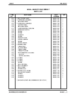
Page 21: ...1 MOTOR ASSEMBLY 26825 099 1 5 IMPELLER 26825 863 1 6 SHAFT KEY 26824 172 1 10 SCREW 26824 378 1 11 VOLUTE CASING 26823 763 1 13 SCREW 26824 406 3 31 RUBBER SEAL 26824 066 1 38 GUIDE SHOE 26824 001 1 41 SCREW 26824 357 3 53 NAME PLATE 38818 055 1 54 RIVET 26824 451 4 INDICATES PARTS RECOMMENDED FOR STOCK ...

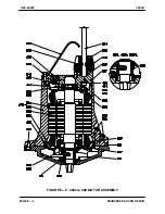
Page 22: ...OM 05229 JSV3H PAGE E 4 MAINTENANCE AND REPAIR FIGURE E 2 26824 988 MOTOR ASSEMBLY ...

Page 23: ...3 1 231 LIFTING HANDLE 26823 532 1 233 SCREW 26824 360 2 234 MOTOR CABLE 26823 312 1 235 RUBBER SEAL 26824 064 1 236 CABLE INLET 26823 341 1 237 ALLEN SCREW 26824 371 3 238 CABLE CLAMP 26823 361 1 244 CONNECTOR SET 26825 429 1 246 STATOR MOTOR HOUSING 26825 532 1 301 STATOR 26825 623 1 302 MOTOR HOUSING 26825 707 1 247 O RING 26824 123 1 251 O RING 26824 128 1 252 O RING 26824 124 1 254 SCREW 2682...

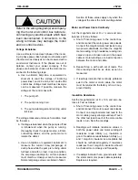
Page 24: ...without draining the oil from the motor See MOTOR DISASSEMBLY If necessary to pry components apart to separate them use levers on both sides of the component and apply pressure even ly Be careful not to mar mating surfaces When removing parts from the rotor shaft assembly be careful not to mar the surface or tapered end of the shaft PUMP END DISASSEMBLY References are to FIGURE E 1 NOTE The volute...

Page 25: ...t and O ring off the shaft 6 Work a pair of stiff wires with hooked ends be tween the seal stationary seat and the shaft and hook the back of the stationary seat Pull the stationary seat out of the bearing housing Remove the stationary seat O ring from the bearing housing If no further disassembly is required refer to IN SPECTION AND CLEANING followed by PUMP END REASSEMBLY MOTOR DISASSEMBLY Refer...

Page 26: ...port ring 208 from the shaft NOTE Because bearings can be damaged while being re moved it is recommended that they be inspected in place The bearings are secured by a press fit onto the shaft If the bearings will not be replaced it is also recom mended that they be cleaned in place see IN SPECTION AND CLEANING 3 If the bearings require replacement use a bearing puller to remove them from the shaft...

Page 27: ...ntly lubri cated When installing the upper bearing 203 on the shaft never press or hit against the outer race balls or ball cage Press only on the inner race A sleeve with the same diameter as the inner race is useful for in stalling the bearing When installing the lower bearing 207 in the bearing housing never press or hit against the inner race balls or ball cage Press only on the outer race A s...

Page 28: ...e motor as indicated in LUBRICATION at the end of SECTION E Installing Motor Cover 1 Clean the exterior of the motor cable 234 with warm water and mild detergent and inspect for obvious damage If required see ELEC TRICAL TESTING in TROUBLESHOOTING SECTION D Do not splice the cable waterproof integri ty must be maintained If repairs are re quired other than at either end replace the entire cable 2 ...

Page 29: ...t switch re move it from the air tight plastic shipping bag prior to installation to allow it to accli mate to local humidity levels before check ing and adjusting the clearance as follows See FIGURE E 3 and install the switch in a simple bell circuit or other test circuit Use a feeler gauge to check clearance between the expander and switch body clearance should be 0 100 inch 2 5 mm 12 After chec...

Page 30: ...lace a clean tissue over the stationary seat seal face and press it into the bearing housing with the seal face up 4 Lubricate the rotating element O ring and in stall it ing the rotating element Slide the rotat ing element and O ring onto the shaft making sure the slot in the element engages the drive pin 5 Place a drop of grease in the cups of the seal clamp to hold the clamp springs 432 in plac...

Page 31: ...f the leak 7 Re run the test after corrective action has been taken TEST 2 1 Install air hoses as in Test 1 This test is conducted with the pump un der power Refer to the wiring diagram and observe all precautions outlined in INSTALLATION SECTION B when connecting the motor cable to the con trol box Otherwise the pump could be damaged and personnel exposed to in jury or death 2 Connect the motor c...

Page 32: ...e the guide shoe to the volute casing 11 with the screws 41 4 See LUBRICATION before returning the pump to service LUBRICATION All references are to FIGURE E 2 The upper screw plug 268 in the motor housing is used for testing only do not add oil through this plug Before installing or removing the screw plugs 268 always clean the area around the plugs to prevent contamination of the oil Discard the...

Page 33: ...lease any pressure in the seal housing 257 2 Remove the second lower screw plug along the flange of the motor housing and through the top plug hole add SAE 10W 30 motor oil un til it escapes from the lower plug hole 3 Lubricate and install new O rings 269 and in stall and tighten the plugs 269 ...

Page 34: ...part claimed to be defective in accordance with the maintenance schedule and or manual which comes with the product No allowance will be made for labor trans portation or other charges incurred by you in connection with such repair or replacement 2 To obtain the above remedy a Immediately notify GR at the address below of the claimed defect in materials or workmanship and provide the serial number...

Reviews: