GORMAN-RUPP PUMPS GRP33-30 Installation, Operation And Maintenance Manual Download Page 15

OM−05850

G-R

TROUBLESHOOTING

PAGE D − 2

PUMP PREVENTIVE MAINTENANCE

The following preventive maintenance information
applies to self-priming centrifugal pumps only. Un-
der normal conditions, the Air Release Valve re-
quires no preventive or routine maintenance. How-
ever, in extreme conditions dust or dirt may clog
the spring cavity, preventing full valve closure.
Check the spring cavity regularly and, if blockage
occurs, flush with clean water.

Since pump applications are seldom identical, and
pump wear is directly affected by such things as
the abrasive qualities, pressure and temperature
of the liquid being pumped, this section is intended
only to provide general recommendations and
practices for pump preventive maintenance. Re-
gardless of the application however, following a
routine preventive maintenance schedule will help
assure trouble-free performance and long life from
your Gorman-Rupp pump. For specific questions
concerning your application, contact your Gor-

man-Rupp distributor or the Gorman-Rupp Com-
pany.

Record keeping is an essential component of a
good preventive maintenance program. Changes
in suction and discharge gauge readings (if so
equipped) between regularly scheduled inspec-
tions can indicate problems that can be corrected
before system damage or catastrophic failure oc-
curs. The appearance of wearing parts should also
be documented at each inspection for comparison
as well. Also, if records indicate that a certain part
(such as the seal) fails at approximately the same
duty cycle, the part can be checked and replaced
before failure occurs, reducing unscheduled down
time.

For new applications, a first inspection of wearing
parts at 250 hours will give insight into the wear rate
for your particular application. Subsequent inspec-
tions should be performed at the intervals shown
on the chart below. Critical applications should be
inspected more frequently.

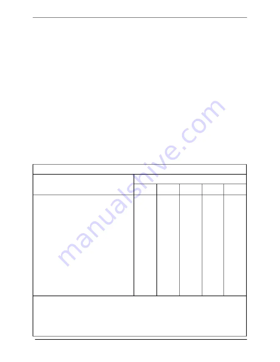
General Condition (Temperature, Unusual

Noises or Vibrations, Cracks, Leaks,
Loose Hardware, Etc.)

I

Pump Performance (Gauges, Speed, Flow)

I

Bearing Lubrication

I

R

Seal Lubrication (And Packing  Adjustment,

If So Equipped)

I

R

V-Belts (If So Equipped)

I

Front Impeller Clearance (Wear Plate)

I

Rear Impeller Clearance (Seal Plate)

I

Check Valve

I

Pressure Relief Valve (If So Equipped)

C

Pump and Driver Alignment

I

Shaft Deflection

I

Bearings

I

Bearing Housing

I

Piping

I

Driver Lubrication − See Mfgr’s Literature

Legend:
 I = Inspect, Clean, Adjust, Repair or Replace as Necessary
C = Clean
R = Replace

* Service interval based on an intermittent duty cycle equal to approximately 4000 hours annually.

Adjust schedule as required for lower or higher duty cycles or extreme operating conditions.

Pump Preventive Maintenance Schedule

Item

Daily

Weekly

Monthly

Semi-

Annually

Annually

Service Interval*

Summary of Contents for GRP33-30

Page 1: ...NY D MANSFIELD OHIO www gormanrupp com GORMAN RUPP OF CANADA LIMITED D ST THOMAS ONTARIO CANADA Printed in U S A e2006 The Gorman Rupp Company INSTALLATION OPERATION AND MAINTENANCE MANUAL WITH PARTS...

Page 2: ...SECTION C PAGE C 1 THEORY OF OPERATION PAGE C 1 ADJUSTMENT PAGE C 1 LEAKAGE PAGE C 2 TROUBLESHOOTING SECTION D PAGE D 1 MAINTENANCE AND REPAIR SECTION E PAGE E 1 AIR RELEASE VALVE DIMENSIONS PAGE E 1...

Page 3: ......

Page 4: ...head If there are any questions regarding the pump or its application which are not covered in this man ual or in other literature accompanying this unit please contact your Gorman Rupp distributor or...

Page 5: ......

Page 6: ...result of valve failure Before attempting to service the Air Re lease Valve 1 Familiarize yourself with this man ual 2 Disconnect or lock out the power source to the pump or isolate the Air Release Va...

Page 7: ......

Page 8: ...eck for and tighten loose attaching hard ware at mating surfaces Air Release Valve Identification Air Release Valves are not readily identifiable by their individual part numbers There are however two...

Page 9: ...eads and should be con nected to a street tee to facilitate cleaning in case the Air Release Valve becomes clogged Connect a bleed line the same size as the valve outlet to the street tee so the line...

Page 10: ...anywhere in the air release piping it must be a full opening ball type valve to prevent plugging by solids Any shut off valve installed in a bypass line must not be left closed during oper ation A cl...

Page 11: ......

Page 12: ...ng cycle Figure C 1 Figure C 1 Valve in Open Position When the pump is fully primed pressure resulting from flow through the valve compresses the inlet chamber diaphragm The barrier liquid on top of t...

Page 13: ...h designed into the valve This leakage path acts as a pressure relief to prevent the valve from becoming hydraulically locked when the pump is shut down This happens most often in a closed system wher...

Page 14: ...BABLE REMEDY VALVE FAILS TO CLOSE Inlet line outlet line or Air Release Valve clogged Clean lines or valve Low discharge head application Adjust restrictor to obtain full valve closure Pump not produc...

Page 15: ...atastrophic failure oc curs The appearance of wearing parts should also be documented at each inspection for comparison as well Also if records indicate that a certain part such as the seal fails at a...

Page 16: ...ION WHICH ARE KEYED TO FIGURE E 2 AND THE ACCOMPANYING PARTS LIST DIMENSIONS INCHES MILLIMETERS Figure E 1 Air Release Valve Dimensions Before installing the Automatic Air Re lease Valve check the che...

Page 17: ...OM 05850 G R MAINTENANCE REPAIR PAGE E 2 PARTSPAGE SECTION DRAWING Figure E 1 GRP33 30 GRP33 30A And GRP33 30B Air Release Valves...

Page 18: ...T AVAILABLE 14 8 COTTER PIN NOT AVAILABLE 1 9 ADJUSTABLE RESTRICTOR NOT AVAILABLE 1 10 RESTRICTOR O RING GRP33 30 S1556 1 RESTRICTOR O RING GRP33 30A 25154 020 1 RESTRICTOR O RING GRP33 30B 25158 520...

Page 19: ...liarize yourself with this man ual 2 Disconnect or lock out the power source to the pump or isolate the Air Release Valve to ensure that it will remain inoperative 3 Allow the pump and liquid to com p...

Page 20: ...cotter pin 8 Unscrew the restric tor from the lower valve body and remove the re strictor O ring 10 Air Release Valve Reassembly Clean the valve body plunger rod and all compo nent parts except the di...

Page 21: ...table restrictor into the hole in the lower valve body until the inboard end of the re strictor is just flush with the bore inside the lower valve body Install the cotter pin 8 through the holes in th...

Page 22: ...rpumps com warranty or call U S 419 755 1280 International 1 419 755 1352 For Canadian Warranty Information Please Visit www grcanada com warranty or call 519 631 2870 THE GORMAN RUPP COMPANY D MANSFI...

Reviews: