17
pump is switched to normal operation.
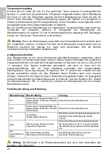
Indicator of errors
and warnings
Error
Description
Solution
Er1
Error - Temperature sensor 2a
(disconnected, faulty
connection, short circuit).
Call your service provider.
Er2
Error - Temperature sensor 2b
(disconnected, faulty
connection, short circuit).
Call your service provider.
tLo
Surrounding temperature too
low.
When the surrounding air temperature rises, the
water pump starts functioning normally.
LEG
Heat pump is operating in the
anti-legionella mode.
When the water temperature in the tank reaches
65 °C, the heat pump starts functioning normally.
Control lamp 3
is flashing
Delayed start of the heating
pump.
The heating pump starts functioning after the time
delay is finished.
WARNING:
Even after switching off with the switch, the elements in the electric control
unit are live!
USE OF ELECTRIC HEATING ELEMENT (only models with electric heating
elements)
The built-in electric heating elements, type SH are designed as backup heating of water in
closed and open type water heaters.
During operation, the heating element and protection tube of the probe should be
sufficiently immersed into water.
Temperature of the electric heater housing should not exceed 80
°C.
The installation should be carried out in compliance with the requirements defined by the
applicable regulations as well as local power supply regulations. The heater may be
connected by an authorised technician only.
Direct the power supply cord through the cable entry to the terminal pin in the electric
heater. Take into account the dimensions of the power supply cord (3x2,5 mm
2
or 5x1,5
mm
2
).
Connect the built-in electric heater to power supply network (in compliance with the wiring
diagram) and take into account the correct voltage values. Before putting into service
check if the wiring of the unit is made in compliance with the wiring diagram.
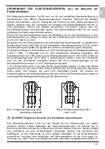
Electric wiring of the heaters with power of 2 kW or more is factory set to three-phase
voltage of 3~400 V (Figure 1) designed for direct regulation. Electric heaters with 2 kW
power can be connected to single-phase voltage of 230 V (Figure 2) or to three-phase
voltage of 400 V (Figure 1), where the star connection should not be connected to the
ground conductor. The bridge connections on the terminal pin should be made of 1,5 mm
2
copper wire.
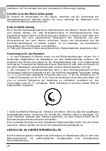
1. Rotate the protective cover to the required position by removing the cover, turn it around
and mount it again. The sealing on the housing should not be moved in any way and be
careful not to damage it. Use original screws with washers. Damages caused by
unprofessional installation of the electric heaters will not be covered by the guarantee.
EN
Summary of Contents for TC 200-1/ZBR
Page 1: ...TC 200 300 ZBR ...
Page 120: ...07 2013 408739 ...


