GOODWIN P30U Operation Manual Download Page 9


P30U Instruction Manual Revision : 1

1st December 2006   

Page 9

4.

PLASMA AND TORCH CONNECTIONS

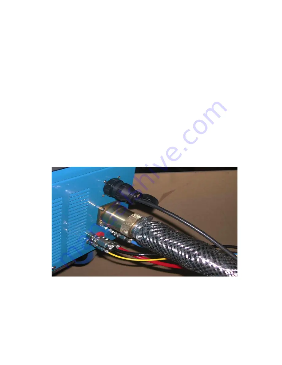
4.1 Connecting the Torch and Plasma Earth Lead to the Power Unit

Note.

Do not run the power unit without the torch connected.

The connections to the power unit are located at the front of the unit.

The PTU torch and umbilical extensions use a specially designed electrical connector for the power,
safety earth, pilot arc, and all other electrical connections.  There is a central pin that carries the
power, a pin for the pilot arc connection and 5 smaller pins for safety monitoring and the diver’s
control switch.  The safety earth is made through the locking sleeve.  There are four hose connectors,
filled with quick acting connectors.

the blue hose is the cooling water to the torch;
the red hose is the cooling water return from the torch

 the black hose carries the plasma air

the yellow hose is a “pneumo” connection to allow the plasma air pressure to
automatically track the working depth

The water connections are not polarised but it is advisable to follow the colour coding.
These connectors are found on the machine front panel and replicated at the socket end of the      ex-
tension umbilicals.
The supervisor’s remote control panel connects to a multiway socket above the torch connectors.

 (Note that this is an “analogue” lamp, therefore it may be illuminated but not at full brightness,
and the indicator (which is “digital”) on the front panel and the supervisors panel still fail to
light because of a poor connection).

When first switching on, allow enough time for the water to circulate through the system.  Top up the
header tank as required. Use only distilled or de-ionised water. (See section 7.1 regarding use of
methanol in freezing conditions).

The two earth connectors (insert and twist clockwise to lock) are located on the left hand side of
the front panel.  An indicator lamp indicates when an earth loop has been successfully made.

Summary of Contents for P30U

Page 1: ...P30U Instruction Manual Revision 1 1st December 2006 Page 1 OPERATION MANUAL for the GOODWIN P30U UNDERWATER AIR PLASMA CUTTING SYSTEM...

Page 2: ...act It is strongly recommended that all users and supervisors familiarisethemselveswiththecontents PRIOR TO COMMENCING USE OF THE SYSTEM and in particular the section on safety precautions which shoul...

Page 3: ...NG WITH STAND OFF 15 5 3 3 CUTTING SPEED 16 5 3 4 PIERCING THICKER MATERIALS WITH A HAND TORCH 17 5 4 Troubleshooting 18 5 5 Consumable Life 18 5 5 1 INTRINSIC LIFE 18 5 5 2 ALIGNMENT 18 5 5 3 TRANSIE...

Page 4: ...he cut is not a hazard to the operator or to others e Protection is necessary against ultraviolet radiation emitted from the arc A helmet or shield with shade glass is recommended Note however that th...

Page 5: ...d personnel should remove the canopy 1 4 Packaging Handling and Transport Should the plasma unit need to be shipped we recommend re use of the original packing crate Also a That the hose set be discon...

Page 6: ...RC is brought close to the work piece MAINARC isTRANSFERRED to the work piece as a jet of high energy which rapidly melts any metal with which it makes contact providingfastcutting lowresidualheatinpu...

Page 7: ...Where the material to be cut forms part of the structure which is earthed or grounded to the mains electricalsupplysystem thenthecuttingcurrentcouldflowthroughthatrouteratherthantheplasma earth lead t...

Page 8: ...filter to establish a proper flow Switch on the machine by rotating the main isolator and pressing the on off button ensuring the emergency stop switch is unlatched Correct phase connection is determ...

Page 9: ...lasma air the yellow hose is a pneumo connection to allow the plasma air pressure to automatically track the working depth The water connections are not polarised but it is advisable to follow the col...

Page 10: ...supervisors panel and a communications procedure to energise the torch The torch will de energise if the diver s switch is released at any time Note that it is good practice to leave the power unit ru...

Page 11: ...5 1 Machine Controls The front panel of the machine provides a range of displays and control gear to ensure correct operation ON OFF BUTTONS Switchesauxiliarycircuitsonandoff ieCompressor waterpump c...

Page 12: ...the air regulator tracks the working depth therefore the pressure gauge shows this operating pressure plus the working depth 1 bar 10m 32 ft TrackingAirRegulator Sets the air flow through the torch t...

Page 13: ...h WATER INDICATOR Indicatesinsufficientwaterflowinthetorch EARTH CURRENTINDICATOR Indicates excessive currents in the supply earth see section 3 2 EARTH SAFETYINDICATOR Indicates a break in the earth...

Page 14: ...will illuminate Note thatthe supervisorspanelwill always need to be reset even ifthe machine has been reset on the front panel To ascertain the absence of air leaks the air regulator should be wound...

Page 15: ...ximity of the work piece or by positioning the torch over the edge of the work piece and starting the pilot arc Underwater and especially at depth it may be necessary to always start very close to the...

Page 16: ...of the plate either by observing the ejected material or by studying the surface of a cut after complet ing a test cut The drag back of the arc is aproximately 30 degrees CUTTING TOO SLOW Arc appears...

Page 17: ...duallybringingitupright aspiercingiscompleted Initiate the pilot arc and lay the torch over at approximately 60 Begintwistingthetorchslowlytowardsaverticalpositiontaking caretoavoidejectedmaterialfrom...

Page 18: ...eerodedslightlyeachtimethearcisstruckeventuallycreatingavisiblecrater The crater can be more than 2mm deep before the electrode is considered to be expired 5 5 2 Alignment Thealignmentandconstructiono...

Page 19: ...e powerunit before removing the nozzle forthis purpose Once a non starting electrodehasbeenusedafewtimes startingusuallyimproves It is not good practice to fire the pilot arc continually in mid air wi...

Page 20: ...BLES which are eroded during the cutting process They consist of a Nozzle b ElectrodeAssemblycomprising Electrode SwirlBush Oring Other parts that may be damaged and replaced by the user are Front Cap...

Page 21: ...eal and the front cap retaining ring as it may be caught between the two seals and preventfittingofthefrontcap Thefrontinsulatormaybereplacedifdamagedusingthespecialtoolprovided Thisisanoperation that...

Page 22: ...or this purpose THIS IS VERYIMPORTANT If the Electrode is not pressed fully home onto the ContactTube the Swirl BushmaybepartlycrushedbytheNozzle andwillinterferewiththeairflow 6 CarefullyscrewtheNozz...

Page 23: ...50Hz 70 amp 98 amp 460v 60Hz 70 amp 98 amp Other voltages and frequencies available to order 6 1 2 Electrical Output Opencircuitvoltage 330 345V dc Typicalarcvoltage 150 200V dc Main arc power 36kW Pi...

Page 24: ...thecompressorisfirstpassed through a cooling radiator and then a coalescing filter to dry it This has an automatic drain The high pressure water pump supplies cooling water to the torch through quick...

Page 25: ...P30U Instruction Manual Revision 1 1st December 2006 Page 25 7 1 1 CircuitDiagram...

Page 26: ...Page 26 P30U Instruction Manual Revision 1 1st December 2006 7 1 2 MachineLayout 18 19 16 20 9 4 6 7 5 10 3 11 29 15 12 14 13 27 28 17 8...

Page 27: ...t Neon 23 Air Pressure Regulator 24 Stop Start Switch 25 Emergancy Stop Switch 26 Reset Switch 27 Water Pump 28 Compressor 29 Solonoid Valve Not Shown Dix Connector Not Shown Power Factor Correction C...

Page 28: ...tomatically EARTH CURRENTINDICATOR Indicatesthemainarccuttingcurrentisflowinginasecondarypath Systemwillstopuntilitisreset when the torch switch is released See section 3 2 for cutting earth requireme...

Page 29: ...removed the torch head may be serviced or repaired If a spare torch and umbilical is available the machine may be put back in service whilst repairs are carried out TORCH BLOCKAGE The water flow in th...

Page 30: ...his dust which may represent a health hazard Use personal protection as necessary Clean or replace the compressor air intake filter Check tightness of all electrical and mechanical connections Check t...

Reviews: