5
2.2.2. Wall Mount
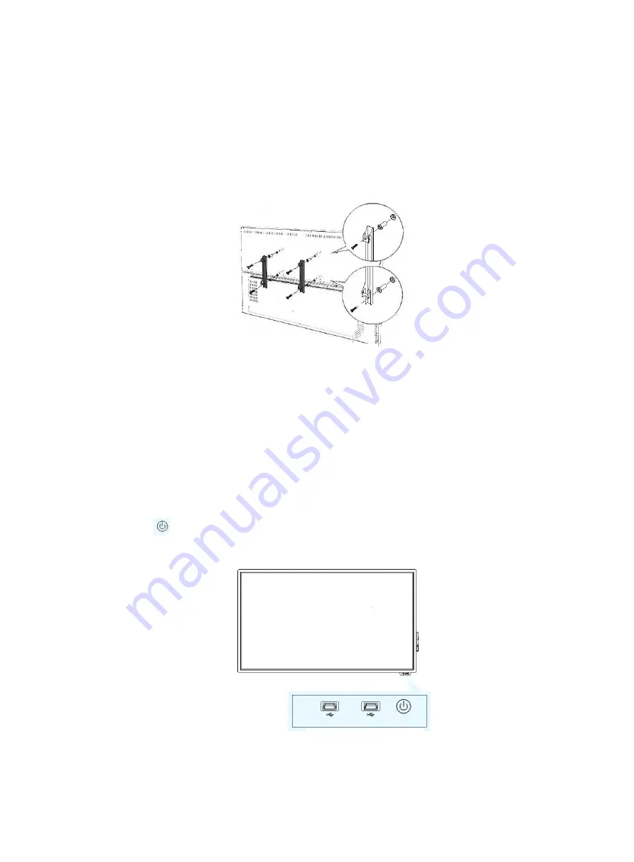
The installation environment needs to be checked in advance due to the heavyweight. The wall should bear
more than 200kg. If the machine is mounted on the wooden wall, please ensure that the thickness at least 2cm,
the load-bearing should over 200kg. Please follow the hole spacing of the product to install, and keep a certain
distance between the product and wall for good ventilation. Please prepare 4 M8 bolts (with a screw length of
50mm) and tighten the bolts. Before installation, please consult a professional or technical for guidance.
(The diagram below is the bracket for GM65S4).
III.
Operation Guide
This chapter is mainly about GM**S4 operation guide including power switch, front interface, dual system
switch, toolbar, network connection and settings, touch operation, screen projection, file saving, etc.
3.1 Power Switch and Front Ports
The conference LCD display has an AC IN power connector on the machine back. Please ensure that the machine
power connector is connected to the appropriate power source. Please confirm that the power cord used matches
with the power outlet voltage, is certified and meets the safety regulations of the country.
The front button of the machine is the power switch. It will turn red when the machine is powered and
turn to blue when the machine starts. Two USB ports on the front support for external terminal connection.
USB port
USB port
Switch
(
Bracket Diagram 2
)


