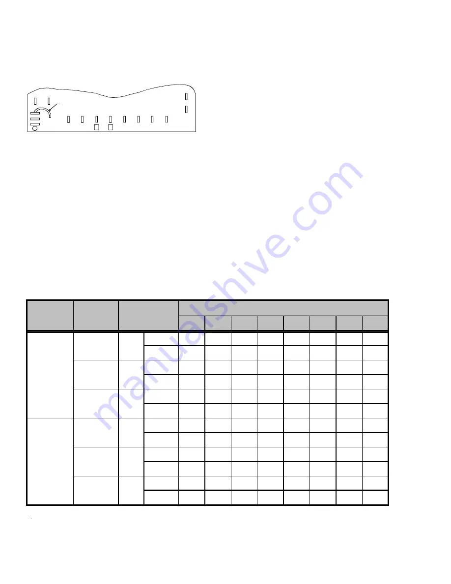
10
calls for heat. At the end of the timing period, the unit’s
defrost cycle will be initiated provided the sensor remains
closed. When the sensor opens (approximately 75° F), the
defrost cycle is terminated and the timing period is reset. If
the defrost cycle is not terminated due to the sensor
temperature, a ten minute override interrupts the unit’s
defrost period.
C
Y
W2
R
R DFT
TEST
DF1
DF2
JUMPER WIRE
90
60
30
A
FIGURE 7
SUGGESTED FIELD TESTING/TROUBLE SHOOTING
1.
Run unit in the heating mode (room thermostat calling for
heat).
2.
Check unit for proper charge.
Note: Bands of frost on the
condenser coil indicate low refrigerant charge.
3.
Shut off power to unit.
4.
Disconnect outdoor fan by removing the purple lead from
“DF2” on defrost control.
5.
Restart unit and allow frost to accumulate.
6.
After a few minutes of operation, the unit’s defrost
thermostat should close. To verify this, check for 24 volts
between “DFT” and “C” on board. If the temperature at the
thermostat is less than 28° F and the thermostat is open,
replace the unit’s defrost thermostat, as it is defective.
7.
When the unit’s defrost thermostat has closed, short the
test pins on the defrost board until the reversing valve shifts,
indicating defrost. This should take up to 21 seconds
depending on what timing period the control is set on. After
defrost initiation, the short must instantly be removed or the
unit’s defrost period will only last 2.3 seconds.
8.
After the unit’s defrost thermostat has terminated, check
the defrost thermostat for 24 volts between “DFT” and “C”.
The reading should indicate 0 volts (open sensor).
9.
Shut off power to unit.
10. Replace outdoor fan motor lead to terminal “DF2” on defrost
board and turn on power.
AIR FLOW MEASUREMENT AND ADJUSTMENT
After reviewing section on DUCTING, proceed with airflow
measurements and adjustments. Unit’s blower curves (in
Specification Sheets) are based on external static pressure
(ESP, in. of W.C.). The duct openings on the unit are
considered internal static pressure, so as long as ESP is
maintained, the unit will deliver the proper air up to the
maximum static pressure listed for the CFM required by the
application (i.e. home, building, etc.)
In general 400 CFM per ton of cooling capacity is a rule of
thumb. Some applications depending on the sensible and
latent capacity requirements may need only 350 CFM or up
to 425 CFM per ton. Check condition space load
requirements (from load calculations) and equipment
expanded ratings data to match CFM and capacity.
Notes:
• Data shown is dry coil. Wet coil pressure drop is approximately 0.1" H2O, for two-row indoor coil; 0.2” H2O, for three-row indoor coil; and 0.3” H2O, for four-row indoor coil.
• Data shown does not include filter pressure drop, approx. 0.08” H
2
O.
• ALL MODELS SHOULD RUN NO LESS THAN 350 CFM/TON.
• Reduce airflow by 2% for 208-volt operation.
0.1
0.2
0.3
0.4
0.5
0.6
0.7
0.8
CFM
1,180
1,125
1,075
1,020
955
875
655
-
WATTS
335
325
315
305
295
275
240
-
CFM
1,350
1,280
1,205
1,130
1,050
985
910
845
WATTS
435
420
405
385
375
350
330
310
CFM
1,450
1,370
1,290
1,205
1,130
1,040
960
885
WATTS
495
480
465
440
425
400
385
370
CFM
1,860
1,800
1,745
1,695
1,650
1,600
1,555
1,500
WATTS
410
425
440
455
470
480
495
500
CFM
1,990
1,945
1,885
1,835
1,785
1,740
1,695
1,645
WATTS
510
520
530
545
555
570
585
590
CFM
2,100
2,045
1,985
1,945
1,895
1,850
1,800
1,750
WATTS
595
610
620
630
645
660
670
680
230
230
230
230
230
230
Model
Speed
Volts
E.S.P (In. of H
2
O)
G
P
H
1
3
36H
2
1
*
G
P
C
1
3
36H
2
1
*
LOW
MED
HIGH
G
P
H
1
3
60H
2
1
*
G
P
C
1
3
60H
2
1
*
"T" 1 LOW
"T" 2 MED
"T" 3 HIGH


