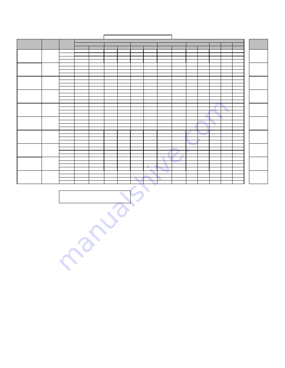
Goodman AC9S80 Service And Troubleshooting Download Page 45

AIRFLOW TABLES

45

GM9S80

0.6

0.7

0.8

CFM

RISE

CFM

RISE

CFM

RISE

CFM

RISE

CFM

RISE

CFM

CFM

CFM

F01^^

658

N/A

585

N/A

545

N/A

495

N/A

444

N/A

390

332

151

F02^

749

40

697

42

652

45

607

49

554

53

509

459

406

F03

925

32

881

34

840

35

800

37

760

39

721

681

645

F04

882

34

841

35

800

37

760

39

719

41

678

641

602

F01^^

659

N/A

599

N/A

542

N/A

490

N/A

437

N/A

383

320

N/A

F02^

1268

35

1221

36

1188

37

1154

38

1122

40

1091

1060

1029

F03

1087

41

1044

43

1008

44

973

46

938

47

905

871

841

F04

1118

40

1070

42

1033

43

997

45

963

46

929

896

865

F01^^

720

N/A

660

N/A

614

N/A

542

N/A

468

N/A

413

359

313

F02^

1289

34

1260

35

1232

36

1194

37

1161

38

1125

1087

1073

F03

1125

40

1089

41

1052

42

1013

44

973

46

947

909

863

F04

1252

36

1198

37

1153

39

1110

40

1069

42

1028

990

953

F01^^

764

N/A

695

N/A

630

N/A

559

N/A

485

N/A

415

358

N/A

F02^

1287

35

1235

36

1191

37

1147

39

1104

40

1062

1020

979

F03

1339

33

1301

34

1258

35

1217

37

1174

38

1131

1090

1048

F04

1396

32

1346

33

1298

34

1257

35

1217

37

1175

1135

1098

F01^^

710

N/A

646

N/A

580

N/A

515

N/A

432

N/A

367

314

274

F02^

1298

46

1255

47

1216

49

1178

50

1140

52

1102

1067

1028

F03

1209

49

1166

51

1124

53

1083

55

1045

57

1005

964

923

F04

1138

52

1091

54

1045

57

1001

59

959

62

920

876

832

F01^^

841

N/A

657

N/A

595

N/A

522

N/A

439

N/A

367

315

N/A

F02^

1141

52

1089

54

1045

57

1001

59

958

62

914

869

823

F03

1311

45

1267

47

1226

48

1189

50

1150

52

1114

1072

1034

F04

1395

42

1347

44

1309

45

1270

47

1233

48

1199

1164

1125

F01^^

831

N/A

750

N/A

671

N/A

588

N/A

501

N/A

405

348

300

F02^

1214

49

1158

51

1103

54

1045

57

989

60

936

883

823

F03

1303

45

1249

47

1191

50

1136

52

1081

55

1028

974

928

F04

1426

42

1375

43

1324

45

1277

46

1229

48

1177

1124

1078

F01^^

837

N/A

752

N/A

671

N/A

576

N/A

501

N/A

426

361

315

F02^

1316

45

1270

47

1218

49

1166

51

1114

53

1061

1000

962

F03

1353

44

1323

45

1286

46

1235

48

1183

50

1131

1085

1040

F04

1587

37

1544

38

1506

39

1459

41

1416

42

1372

1323

1281

F01^^

802

N/A

724

N/A

637

N/A

551

N/A

468

N/A

389

342

294

F02^

1405

53

1356

55

1308

57

1262

59

1210

61

1155

1102

1057

F03

1574

47

1531

48

1484

50

1440

51

1392

53

1357

1306

1256

F04

1619

46

1575

47

1526

49

1489

50

1446

51

1404

1355

1313

F01^^

851

N/A

774

N/A

692

N/A

615

N/A

535

N/A

470

411

359

F02^

1677

53

1629

55

1583

56

1540

58

1498

59

1449

1399

1349

F03

1537

58

1489

60

1444

62

1404

63

1365

65

1322

1272

1211

F04^^

1416

N/A

1365

N/A

1315

N/A

1267

N/A

1220

N/A

1163

1106

1048

20-50

20-50

20-50

35-65

35-65

35-65

35-65

35-65

40-70

W/W1

*M9S800603A*

W/W1

*M9S800603B*

W/W1

*M9S800604B*

W/W1

*M9S800803B*

W/W1

*M9S800804B*

W/W1

TEMP RANGE

25-55

W/W1

*M9S800403A*

MODEL

THERMOSTAT 

CALL

^DEFAULT & RECOMMENDED

^^NOT RECOMMENDED FOR HEATING

NOTE:

HEATING AIRFLOW

TAP #

EXTERNAL STATIC PRESSURE, (INCHES WATER COLUMN)

0.1

0.2

0.3

0.4

0.5

*M9S800804C*

W/W1

*M9S800805C*

W/W1

*M9S801005C*

W/W1

*M9S801205D*

Summary of Contents for AC9S80

Page 1: ...oduct to provide our customers with quality products It is possible however that during its lifetime a product may require service Products should be serviced only by a qualified service technician who is familiar with the safety procedures required in the repair and who is equipped with the proper tools parts testing instruments and the appropriate service manual REVIEW ALL SERVICE INFORMATION IN...

Page 2: ...line for dealers Your telephone company will bill you for the call WARNING This unit should not be connected to or used in conjunction with any devices that are not design certified for use with this unit or have not been tested and approved by the manufacturer Serious property damage or personal injury reduced unit performance and or hazardous conditions may result from the use of devices that ha...

Page 3: ...ionner au sein de la zone confinée WARNING If the information in these instructions is not followed exactly a fire or explosion may result causing property damage personal injury or loss of life do not store or use gasoline or other flammable vapors and liquids in the vicinity of this or any other appliance WHAT TO DO IF YOU SMELL GAS Do not try to light any appliance Do not touch any electrical s...

Page 4: ...A Brand Configuration M Upflow Horizontal Major Revision C Downflow Horizontal A Initial Release B 1st Revision Nox Motor 9 Nine Speed ECM Cabinet Width A 14 Gas Valve B 17 5 C 2 Stage C 21 S 1 STAGE D 24 5 Maximum CFM 3 1200 CFM AFUE 4 1600 CFM 80 80 AFUE 92 92 AFUE 5 2000 CFM 96 96 AFUE 97 97 AFUE MBTU h 030 30 000 BTU h 080 80 000 BTU h 040 40 000 BTU h 100 100 000 BTU h 060 60 000 BTU h 120 12...

Page 5: ...ce circulator blower and outdoor cooling unit run integrated control module monitors safety circuits continuously 6 R and Y thermostat contacts open completing the call for cool 7 Outdoor fan and compressor are de energized 8 Circulator blower is de energized following a fixed for ty five 65 second cool off delay period 9 Furnace awaits next call from thermostat Fan Only Mode The normal operationa...

Page 6: ...ollow the humidifier or air cleaner manufacturers in structions for locating mounting grounding and controlling these accessories If it is necessary for the installer to supply additional line voltage wiring to the inside of the furnace the wiring must conform to all local codes and have a minimum temperature rating of 105 C All line voltage wire splices must be made inside the furnace junction bo...

Page 7: ...s are to be made through the 1 4 quick connect terminals provided on the furnace integrated control module The humidifier and electronic air cleaner hot terminals are identified as HUM H and EAC H The humidifier and electronic air cleaner neutral terminals are identified as NEUTRAL All field wiring must conform to applicable codes Connections should be made as shown If it is necessary for the inst...

Page 8: ...lve The system will energize the Induced draft blower The pre purge period begins once the pressure switch is detected closed 24 VAC on Pin 5 After the completion of pre purge the control will energize the igniter After completion of the ignitor warm up period The gas valve is energized The ignitor is de energized as soon as flame is sensed After 30 seconds the indoor blower is energized on heatin...

Page 9: ...ied the compressor is de energized and the Cool Mode Fan Off Delay period begins Following the Cool Mode Fan Off Delay period the cool circulator and air cleaner relay are de energized Cooling Mode Speed Selection To change the main blower speed in COOLING mode fol low the following steps 1 Press the left or right switch until LED displays AC1 for single stage COOLING or AC2 for two stage COOLING ...

Page 10: ... 2 before touching control or wires 4 Discharge any static electricity from your body to ground before removing a new control from its con tainer Follow Steps 1 through 3 if installing the control on a furnace Return any old or new controls to their containers before touching any ungrounded object Product Application This product is designed for use as a residential home gas furnace It is not desi...

Page 11: ...quently contaminated by any of the above substances This protects the non direct vent furnace fromairbornecontaminants Toensurethattheenclosed non direct vent furnace has an adequate supply of combustion air vent from a nearby uncontaminated room or from outdoors Refer to the Combustion and Ventilation Air Requirements section in this manual or the installation instructions for details If the furn...

Page 12: ...d spillage at the draft hood relief opening after 5 minutes of main burner operation Use the flame of a match or candle f After it has been determined that each appli ance connected to the venting system properly vents when tested as outlined above return doors windows exhaust fans fireplace damp ers and any other gas burning appliance to their previous conditions of use g If improper venting is o...

Page 13: ...oor air shall be determined in accordance with the method in 9 3 2 1 or 9 3 2 2 except that where the air infiltration rate is known to be less than 0 40 ACH the method in 9 3 2 2 shall be used The total required volume shall be the sum of the required volume calculated for all appliances locat ed within the space Rooms communicating directly with the space in which the appliances are installed th...

Page 14: ...ilation louvers each end of attic Figure A 9 3 3 1 1 b All Combustion Air From Outdoors through Ventilated Attic 2 Where communicating with the outdoors through horizon tal ducts each opening shall have a minimum free area of 1 in 2 2000 Btu hr 1100 min2 kW of total input rating of all appliances in the enclosure See Figure A 9 3 3 1 2 Furnace Water Heater Chimney or Gas Vent NOTE The air duct ope...

Page 15: ...ded to prevent the main burn er form igniting should the louver fail to open during burner startup and to shut down the main burner if the louvers close during burner operation 9 3 8 Combustion Air Ducts Combustion air ducts shall comply with 9 3 8 1 through 9 3 8 8 9 3 8 1 Ducts shall be constructed of galvanized steel or a material having equivalent corrosion resistance strength and rigidity Exc...

Page 16: ...ctions section of this manual for instructions Masonry Chimneys WARNING Possibility of property damage personal injury or death Damaging condensation can occur inside masonry chimneys when a single fan assisted Category 1 appliance 80 AFUE fur nace is vented without adequate dilution air Do not connect an 80 furnace to a masonry chimney unless the furnace is common vented with the draft hood equip...

Page 17: ... termination require ments but all other requirements in the checklist can be met it may be possible for a mason to extend the chimney If this will not be practical see Fix 1 2 Min 2 Min 3 Min 10 or Less Wall or Parapet Chimney Ridge 2 Min 10 or Less 3 Min Chimney Termination 10 Feet Or Less From Ridge Wall or Parapet Wall or Parapet Chimney NOTE No Height above parapet required when distance from...

Page 18: ...can probably be rehung so as to be acceptable A thimble or fire stop may be helpful here Flexible liners should be hung straight or nearly straight If it is spiraled in the chimney and in good condition it should be rehung To do this break the top seal pull up and cut off the excess liner length and refit the top seal Use caution when doing this as the cut edges of flexible liners may be sharp The...

Page 19: ...alled rather than an 80 The 90 furnace can be vented hori zontally or vertically through PVC pipe Fix 3 Rebuild the Crown If the chimney crown is damaged a qualified mason must repair it in accordance with nationally recognized building codes or standards One such standard which may be refer enced is the Standard for Chimneys Fireplaces Vents and Solid Fuel Burning Appliances ANSI NFPA 211 Fix 4 R...

Page 20: ...fe and proper furnace operation All conversions must be performed by a qualified installer or service agency This furnace is shipped from the factory configured for nat ural gas at standard altitude Propane gas installations re quire an orifice change to compensate for the energy con tent difference between natural and propane gas High altitude installations may require both a pressure switch and ...

Page 21: ...ng furnace operation by the integrated control module As shipped the valve is configured for natural gas The valve is field convertible for use with propane gas by using the appropriate propane gas conversion kit Taps for mea suring the gas supply pressure and manifold pressure are provided on the valve NOTE The gas supply pressure on White Rodger J model gas valve used on single stage furnaces ca...

Page 22: ...s for testing Higher pressure may damage the gas valve and cause subsequent overfiring resulting in heat exchanger failure Disconnect this unit and shutoff valve from the gas supply piping system be fore pressure testing the supply piping system with pressures in excess of 1 2 psig 3 48 kPa Isolate this unit from the gas supply piping system by closing its external manual gas shut off valve before...

Page 23: ...multiply by 1 130 To convert to capacities at 5 psig settings multiply by 0 879 3 8 1 2 5 8 3 4 7 8 1 2 3 4 1 1 1 4 1 1 2 10 39 92 199 329 501 275 567 1 071 2 205 3 307 20 26 62 131 216 346 189 393 732 1 496 2 299 30 21 50 107 181 277 152 315 590 1 212 1 858 40 19 41 90 145 233 129 267 504 1 039 1 559 50 18 37 79 131 198 114 237 448 913 1 417 60 16 35 72 1 211 187 103 217 409 834 1 275 80 13 29 62...

Page 24: ...he return duct connected to the furnace NOTE Ductwork must never be attached to the back of the furnace Supply and return connections to the furnace may be made with flexible joints to reduce noise transmission if desired If a central return is used a connecting duct must be installed between the unit and the utility room wall so the blower will not interfere with combustion air or draft The room ...

Page 25: ... but must be provided by the installer for proper furnace operation Remember that dirty filters are the most common cause of inadequate heating or cooling performance WARNING HIGH VOLTAGE Disconnect ALL power before servicing re moving the filter or performing any mainte nance Multiple power sources may be present Failure to do so may cause property damage personal injury or death Maintenance Impr...

Page 26: ...rts Check the burner flames for 1 Stable soft and blue 2 Not curling floating or lifting off Burner Flame Test Equipment Proper test equipment for accurate diagnosis is as essential as regular hand tools The following is a must for every service technician and ser vice shop 1 Thermometers or thermocouple meter optional To measure temperatures 2 Multi Meter To measure amperage and voltage to test c...

Page 27: ...82 164 327 655 1636 37 97 195 486 12 75 150 300 600 1500 38 23 47 95 189 474 13 69 138 277 555 1385 39 92 185 462 14 64 129 257 514 1286 40 22 45 90 180 450 15 60 120 240 480 1200 41 176 439 16 56 113 225 450 1125 42 21 43 86 172 429 17 53 106 212 424 1059 43 167 419 18 50 100 200 400 1000 44 41 82 164 409 19 47 95 189 379 947 45 20 40 80 160 400 20 45 90 180 360 900 46 78 157 391 21 43 86 171 343...

Page 28: ...mple 90 000 BTU HR Calculated Gas Input in this example 92 250 BTU HR This example is within the 5 tolerance input and does not need adjustment CAUTION Always connect a manometer to the outlet tap at the gas valve before adjusting the pressure regulator In no case should the final manifold pressure vary more than plus or minus 3 inches water column from 3 5 inches water column for natural gas or 1...

Page 29: ...ng purposes Some transformers will display phasing symbols as shown in the illustration to the left to assist in determining proper transformer phasing Checking for polarization and phasing should become a habit in servicing Let s start now TRANSFORMER SECONDARY PRIMARY GND C R LINE VOLTAGE L1 HOT LINE VOLTAGE NEUTRAL METER READS 24 VOLTS METER READS 120 VOLTS GND C R N L1 GND C R N L1 READS 96 VO...

Page 30: ... be replaced replace with AWM 105 C 2 64 thick insulation of the same gauge or its equivalent CHECKING THERMOSTAT WIRING WARNING Disconnect ALL power before servicing 1 Remove the blower compartment door to gain access to the thermostat low voltage wires located at the fur nace integrated control module terminals 2 Remove the thermostat low voltage wires at the fur nace control panel terminal boar...

Page 31: ...ent of trans former and check and or repair of control circuit rein stall blower compartment door 8 Turn on electrical power and verify proper unit operation CHECKING AIR CIRCULATOR BLOWER MOTOR WARNING Disconnect ALL power before servicing 1 Remove blower compartment door to gain access to the circulator blower motor and integrated ignition control 2 Check for any obstruction that would keep the ...

Page 32: ...ed If an air conditioner coil or Electronic Air Cleaner is used in conjunction with the furnace the readings must also include theses components as shown in the following drawing 4 Consult proper tables for the quantity of air If the total external static pressure exceeds the minimum or maximum allowable statics check for closed dampers registers undersized and or oversized poorly laid out duct wo...

Page 33: ... following drawing for the location of the primary limit Location of Primary Limit Primary Limit Control Location 80 Upflow Furnace Shown Counterflow Similar Style 1 drawing illustrates the Primary Limit used on the 80 furnaces Style 1 WARNING HIGH VOLTAGE Disconnect ALL power before servicing or changing any electrical wiring Multiple pow er sources may be present Failure to do so may cause prope...

Page 34: ...6 six times indicating a trip of the rollout switch On some models this also indicates an open control board fuse WARNING Line Voltage now present 1 Remove the burner compartment door to gain access to the rollout switch es mounted to burner bracket The servicer should reset the ignition control by opening and closing the thermostat circuit Then look for the ignitor glowing which indicates there i...

Page 35: ...RS The main burners are used to provide complete combustion of various fuels in a limited space and transfer this heat of the burning process to the heat exchanger Proper ignition combustion and extinction are primarily due to burner design orifice sizing gas pressure primary and secondary air vent and proper seating of burners 023 027 Beckett Burner WARNING Disconnect ALL gas and electrical power...

Page 36: ...A GAS STREAM B The length of Dimension A determines the angle of Gas Stream B DENT OR BURR GAS STREAM B A dent or burr will cause a severe deflection of the gas stream CHECKING GAS PRESSURE Gas Supply Pressure Measurement CAUTION To prevent unreliable operation or equipment damage the inlet gas supply pressure must be as specified on the unit rating plate with all other household gas fired applian...

Page 37: ...d repair and then reinstall burner compart ment door 8 Turn on electrical power and verify proper unit operation Gas Manifold Pressure Measurement and Adjustment CAUTION To prevent unreliable operation or equipment damage the gas manifold pressure must be as specified on the unit rating plate Only minor adjustments should be made by adjusting the gas valve pressure regulator NOTE Use adapter kit 0...

Page 38: ...ion CHECKING FOR FLASHBACK Flashback will also cause burning in the burner venturi but is caused by the burning speed being greater than the gas air flow velocity coming from a burner port Flashback may occur at the moment of ignition after a burn er heats up or when the burner turns off The latter is known as extinction pop Since the end results of flashback and delayed ignition can be the same b...

Page 39: ...d by the gas supplier to determine the proper orifice size CHECKING FOR DELAYED IGNITION Delayed ignition is a delay in lighting a combustible mixture of gas and air which has accumulated in the combustion chamber Furnace design makes this extremely unlikely unless safety controls have been by passed or tampered with Never by pass or alter furnace controls If delayed ignition should occur the foll...

Page 40: ...e control will de energize the gas valve and retry for ignition or lockout The following drawings illustrate from a bottom view the ap proximate distances for the ignitor and flame sensor to the gas in shot burner You will note they are in the main burner stream not in the carry over ports as shown in the following figure Flame Sensor Models with Integrated Ignition Control Flame Sensor Probe 80 U...

Page 41: ... 0 06 0 85 0130F00505 M9S800804B 0 70 0 06 0 85 0130F00505 M9S800804C 0 75 0 07 0 90 0130F00506 M9S800805C 0 75 0 07 0 90 0130F00506 M9S801005C 0 70 0 06 0 85 0130F00505 M9S801205D 0 80 0 05 0 95 0130F00507 C9S800403A 0 60 0 06 0 75 0130F00504 C9S800603A 0 60 0 06 0 75 0130F00504 C9S800804B 0 60 0 06 0 75 0130F00504 C9S800805C 0 60 0 06 0 75 0130F00504 C9S801005C 0 80 0 05 0 95 0130F00507 M9S80 C9...

Page 42: ...A F02 1141 1089 1045 1001 958 914 869 823 F03 1311 1267 1226 1189 1150 1114 1072 1034 F04 1395 1347 1309 1270 1233 1199 1164 1125 F05 1490 1447 1407 1373 1336 1303 1269 1237 F06 1553 1510 1469 1435 1401 1368 1335 1300 F07 1593 1548 1508 1474 1440 1409 1376 1343 F08 1776 1735 1695 1661 1628 1601 1570 1542 F09 1853 1812 1773 1739 1708 1679 1650 1623 F01 831 750 671 588 501 405 348 300 F02 1214 1158 ...

Page 43: ...67 315 N A F02 1141 1089 1045 1001 958 914 869 823 F03 1311 1267 1226 1189 1150 1114 1072 1034 F04 1395 1347 1309 1270 1233 1199 1164 1125 F05 1490 1447 1407 1373 1336 1303 1269 1237 F06 1553 1510 1469 1435 1401 1368 1335 1300 F07 1593 1548 1508 1474 1440 1409 1376 1343 F08 1776 1735 1695 1661 1628 1601 1570 1542 F09 1853 1812 1773 1739 1708 1679 1650 1623 F01 831 750 671 588 501 405 348 300 F02 1...

Page 44: ... 657 595 522 439 367 315 N A F02 1141 1089 1045 1001 958 914 869 823 F03 1311 1267 1226 1189 1150 1114 1072 1034 F04 1395 1347 1309 1270 1233 1199 1164 1125 F05 1490 1447 1407 1373 1336 1303 1269 1237 F06 1553 1510 1469 1435 1401 1368 1335 1300 F07 1593 1548 1508 1474 1440 1409 1376 1343 F08 1776 1735 1695 1661 1628 1601 1570 1542 F09 1853 1812 1773 1739 1708 1679 1650 1623 F01 831 750 671 588 501...

Page 45: ...1089 54 1045 57 1001 59 958 62 914 869 823 F03 1311 45 1267 47 1226 48 1189 50 1150 52 1114 1072 1034 F04 1395 42 1347 44 1309 45 1270 47 1233 48 1199 1164 1125 F01 831 N A 750 N A 671 N A 588 N A 501 N A 405 348 300 F02 1214 49 1158 51 1103 54 1045 57 989 60 936 883 823 F03 1303 45 1249 47 1191 50 1136 52 1081 55 1028 974 928 F04 1426 42 1375 43 1324 45 1277 46 1229 48 1177 1124 1078 F01 837 N A ...

Page 46: ... 1713 1677 1642 1611 1576 1549 1518 F06 1309 1261 1218 1182 1142 1103 1064 1025 F07 1580 1534 1495 1459 1429 1390 1356 1324 F08 1523 1483 1438 1403 1370 1336 1299 1266 F09 1643 1599 1562 1525 1491 1462 1431 1394 F01 1022 813 674 585 511 431 334 282 F02 1453 1407 1332 1259 1190 1143 1064 1003 F03 1176 1105 1020 935 864 797 729 673 F04 1710 1660 1613 1560 1505 1424 1353 1296 F05 1843 1786 1747 1690 ...

Page 47: ...1753 1713 1677 1642 1611 1576 1549 1518 F06 1309 1261 1218 1182 1142 1103 1064 1025 F07 1580 1534 1495 1459 1429 1390 1356 1324 F08 1523 1483 1438 1403 1370 1336 1299 1266 F09 1643 1599 1562 1525 1491 1462 1431 1394 F01 1022 813 674 585 511 431 334 282 F02 1453 1407 1332 1259 1190 1143 1064 1003 F03 1176 1105 1020 935 864 797 729 673 F04 1710 1660 1613 1560 1505 1424 1353 1296 F05 1843 1786 1747 1...

Page 48: ...4 1229 1193 F05 1753 1713 1677 1642 1611 1576 1549 1518 F06 1309 1261 1218 1182 1142 1103 1064 1025 F07 1580 1534 1495 1459 1429 1390 1356 1324 F08 1523 1483 1438 1403 1370 1336 1299 1266 F09 1643 1599 1562 1525 1491 1462 1431 1394 F01 1022 813 674 585 511 431 334 282 F02 1453 1407 1332 1259 1190 1143 1064 1003 F03 1176 1105 1020 935 864 797 729 673 F04 1710 1660 1613 1560 1505 1424 1353 1296 F05 ...

Page 49: ...1348 44 1308 45 1270 47 1230 48 1196 1158 1123 F04 1459 41 1414 42 1371 43 1336 44 1297 46 1264 1229 1193 F01 1022 N A 813 N A 674 N A 585 N A 511 N A 431 334 282 F02 1453 41 1407 42 1332 45 1259 47 1190 50 1143 1064 1003 F03 1176 N A 1105 N A 1020 N A 935 N A 864 N A 797 729 673 F04 1710 35 1660 36 1613 37 1560 38 1505 39 1424 1353 1296 F01 956 N A 777 N A 675 N A 587 N A 468 N A 377 324 296 F02 ...

Page 50: ...set at 7 Secs Adjustments can be made in 7 Secs increments from0 to 35 Secs Cool Off Delay Delay Seconds Default set at 65 Secs Adjustments can be made in 5 Secs increments from 0 to 120 Secs Blower Speed for Gas Heat Mode xx xx Blower Speed Number F01 F02 Gas Heat On Delay Delay Seconds Default set at 30 Secs Adjustments can be made in 5 Secs increments from 5 to 30 Secs Gas heat Off Delay Delay ...

Page 51: ...1 STAGE STATUS CODES 51 Idle Continous Fan Compressor Cooling Low Stage Compressor Cooling High Stage Gas heat Single Stage Control OEM test Mode Mode Main Menu STATUS MENU ...

Page 52: ...tor blower motor Correct speed or replace blower motor if necessary Loose or improperly connected wiring in high limit circuit Tighten or correct wiring connection Flame sensed with no call for heat Correct short at flame sensor or in flame sensor wiring Short to ground in flame sense circuit Lingering burner flame Slow closing gas valve Open fuse Replace fuse Short in low voltage wiring Locate an...

Page 53: ...control module Blown fuse or tripped circuit breaker Correct condition which caused fuse to open replace fuse Integrated control module is non functional Replace non functional integrated control module Furnace fails to operate Grounding fault Poor neutral connection Verifyneutral wire connection to furnace continuityto ground source Furnace fails to operate Open roll out switch Check for correct ...

Page 54: ...TEMPERATURE RATING OF AT LEAST 105v C USE COPPER CONDUCTORS ONLY 4 UNIT MUST BE PERMANENTLY GROUNDED AND CONFORM TO N E C AND LOCAL CODES 5 TO RECALL THE LAST 6 FAULTS MOST RECENT TO LEAST RECENT DEPRESS SWITCH FOR MORE THAN 2 SECONDS WHILE IN STANDBY NO THERMOSTAT INPUTS COLOR CODES PK PINK BR BROWN WH WHITE BL BLUE GY GRAY RD RED YL YELLOW OR ORANGE PU PURPLE GN GREEN BK BLACK 1 2 3 4 5 6 7 8 9 ...

Page 55: ...t contact us Amana Brand Products http www amana hac com about us contact us You can also scan the QR code on the right for the product brand you purchased to be directed to the feedback page GOODMAN BRAND AMANA BRAND is a registered trademark of Maytag Corporation or its related companies and is used under license All rights reserved Copyright 2021 Goodman Manufacturing Company L P ...

Reviews: