DE | EN
Betriebsanleitung | User manual
Stereo Audio-/Video-Modulator | Audio/Video Modulator
67249
REV2020-12-09
V2.1 ir
Änderungen vorbehalten. | Subject to change without notice.
Goobay
®
by Wentronic GmbH | Pillmannstraße 12
38112 Braunschweig | Germany
- 2 -
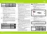
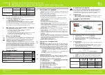
Es gibt 3 Möglichkeiten bei der Funktion-Bit-Anzeige: 0, 1, 2.
Funktions-Bit-
Anzeige
Daten-Bit-
Anzeige
Einstellung
Audiosystem
0
0
4,5 MHz
0
1 (Vorgabe)
5,5 MHz
0
2
6,0 MHz
0
3
6,5 MHz
Signalgenerator
1
0 (Vorgabe)
Normalgebrauch
1
1
Testsignal an
A/V-Übertragungsrate
2
0
12 dB
2
1 (Vorgabe)
16 dB
5. Betätigen Sie den "MODE"-Taster um den Funktionsmodus wieder zu
verlassen.
5.3
Auswahl des Fernsehsystems
1. Wählen Sie mittels Moduswahltaste "MODE" (9) das gewünschte
Fernsehsystem
aus:
EU = Europäisches System, IT = Italienisches System.
2. Wählen Sie den gewünschten Kanal durch Drücken der "UP"- bzw.
"DOWN"-Taste
aus.
Bei gedrückter "UP" -Taste, wechselt der Kanal aufwärts zum nächsten
Kanal.
Bei gedrückter "DOWN"-Taste wechselt der Kanal abwärts zum vorheri-
gen
Kanal.
Angaben zu den Kanälen und Fequenzen finden Sie auf Seite 11.
6 Wartung, Pflege, Lagerung und Transport
Die Produkte sind wartungsfrei.
•
Verwenden Sie zum Reinigen nur ein trockenes und weiches Tuch.
• Verwenden Sie keine Reinigungsmittel und Chemikalien.
•
Lagern Sie das Produkt kühl und trocken.
•
Lagern Sie das Produkt bei längerem Nichtgebrauch für Kinder unzu-
gänglich und in trockener und staubgeschützter Umgebung.
• Heben Sie die Originalverpackung für den Transport auf.
7 Entsorgungshinweise
Elektrische und elektronische Geräte dürfen nach der europäischen
WEEE Richtlinie nicht mit dem Hausmüll entsorgt werden. Deren Be-
standteile müssen getrennt der Wiederverwertung oder Entsorgung zu
geführt werden, weil giftige und gefährliche Bestandteile bei unsachge-
mäßer Entsorgung die Gesundheit und Umwelt nachhaltig schädigen
können.
Sie sind als Verbraucher nach dem Elektrogesetz (ElektroG)
verpflichtet, elektrische und elektronische Geräte am Ende ihrer Lebens-
dauer an den Hersteller, die Verkaufsstelle oder an dafür eingerichtete,
öffentliche Sammelstellen kostenlos zurück zugeben. Einzelheiten
dazu regelt das jeweilige Landesrecht. Das Symbol auf dem Produkt,
der Betriebsanleitung und/oder der Verpackung weist auf diese Bestim-
mungen hin. Mit dieser Art der Stoff trennung, Verwertung und Entsor-
gung von Altgeräten leisten Sie einen wichtigen Beitrag zum Schutz
unserer Umwelt.
WEEE Nr.: 82898622
8 Verwendete Symbole
Nur zur Verwendung im Innenbereich
IEC 60417- 5957
Wechselspannung
IEC 60417- 5032
Gleichspannung
IEC 60417- 5031
Polarität des Gleichstrom-Netzanschlusses
IEC 60417- 5926
Schutzklasse II
IEC 60417- 5172
Recycling
ISO 7001 - PI PF 066
1 Safety Instructions
• Read the user manual completely and carefully before use.
The user manual is part of the product and contains important information
for correct use.
• Keep this user manual.
The user manual must be available for uncertainties and passing the
product.
• In case of emergency, during thunderstorms and after use, pull the
product on its plug housing!
• Do not open the housing.
• Do not modify or disassemble product and accessories.
• Do not short-circuit connectors and circuits.
• Use product, product parts and accessories only in perfect condition.
•
In case of questions, defects, mechanical damage, trouble and other
problems, non-recoverable by the documentation, contact your dealer
or
producer.
• Place, install and transport product, product parts and accessories in a
safe
way.
Not meant for children. The product is not a toy!
• Secure packaging, small parts and insulation against accidental use.
•
Avoid stresses such as heat and cold, moisture and direct sunlight,
microwaves, vibrations and mechanical pressure.
• Do not cover the product.
• Keep enough space around all devices for a good ventlation and free
motion and to avoid damages.
• Use only the supplied power supply.
• Install the system and devices attached to it in a way that persons cannot be
injured, or objects not be damaged for example by dropping or stumbling.
Risk of injury by stumbling and falling.
2 Description and Function
2.1 Product
With the Stereo Audio/Video Modulator, you can feed signals from your
audio/video output devices (e.g. DVD player, SAT receiver, camcorder or
surveillance camera) into your home network via antenna signals, making
them receivable on all TV sets. The stereo audio/video modulator is special-
ly designed for use with devices without their own modulator.
• Converts picture and sound signals (stereo) from DVD recorders and
digital cameras into high-frequency signals (VHF/UHF).
• Frequencies of the output channel can be displayed via LED.
• Channels adjustable via up/down keys.
2.2
Scope of delivery
Audio/Video Modulator, power supply unit, SAT connection cable
(F plug to IEC plug), SAT connection cable (F plug to IEC socket), Scart
audio/video
cable , user manual
2.3
Operating elements and product parts
1
DC
input
2
On/Off switch
3
HF signal input
4
HF signal output (TV connection)
5
Operation LED
6
LED display
7
Channel selection key "UP
8
Channel selection key "DOWN
9
Mode selection key "MODE
10
Analogue audio input left
11
Analogue audio input right
12
Video input
13
Power supply unit
14
Scart audio/video cable
15
SAT connection cable (F plug to IEC plug)
16
SAT connection cable (F plug to IEC socket)
3 Intended Use
We do not permit using the device in other ways like described in chapter
"Description and Function" or in the "Safety Instructions". Use the product
only in dry interior rooms. Not attending to these regulations and safety
instructions might cause fatal accidents, injuries, and damages to per-
sons and property.
4 Preparation
•
Compare the specifications of all used devices to ensure compatibility.
• Check the scope of delivery for completeness and integrity.
5 Connection and Operation
5.1 Connection
1.
Connect the devices as shown in Fig. 2.
1
SAT connection cable (F plug to IEC socket)
2
Antenna socket
3
Television sets
4
SAT connection cable (F plug to IEC plug)
5
Stereo audio/video modulator
6
Scart audio/video cable
7
Video / DVD device
8
Power socket
9
Power supply
5.2
Operation
1.
Switch on all connected devices and the Stereo Audio/Video Modulator.
The operating LED (5) lights up when power is applied and the Stereo
Audio-/Video-Modulator is switched on.
2. Press the "UP" (7) and "DOWN" (8) keys simultaneously to enter the
function
menu.
The display looks as shown in Fig. 3
3. Press the "DOWN" key to set the function bit display.
4. Press the "UP" key to set the data bit display.
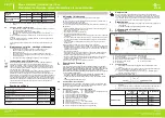
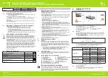
There are 3 possibilities for the function bit display: 0, 1, 2.
Function bit
display
Data bit
display
Settings
Audio system
0
0
4,5 MHz
0
1 (preset)
5,5 MHz
0
2
6,0 MHz
0
3
6,5 MHz


