background image


-

5-


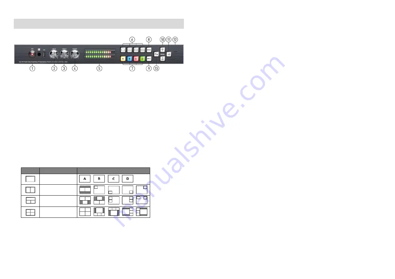
OPERATION APPROACH 

Method A: Front Panel Control 


1.


Recording Button 

To start/stop record 
(1)


LED Solid Red: The USB flash drive is connecting to the product 

(2)


LED Slow Blink: The device is recording 

(3)


LED Fast Blink: The device is in the process of saving file 

2.


Line In Volume Knob


To adjust the line in sound level 

3.


HDMI In Volume Knob


To adjust the HDMI in sound level 

4.


Master Volume Knob


To adjust the line in and HDMI in sound level together 

5.


LED VU Meter Display


To show audio output activity 

6.


Video Layout Selected Button


Select full screen, dual-view, triple-view and quad-view mode. User can switch default layout mode 
by repressing video layout button. 

Button 

Layout Mode 

Default layout mode 


Full screen mode 


Dual-view mode 


Triple-view mode 


Quad-view mode 


7.


Windows Selected Button


User can assign arbitrary video source to every display windows. Firstly, press one of the windows 
A-D buttons. Next, press one of input 1-4 buttons to select the source of selected windows. 
(1)


Windows A (Yellow):   

(2)


Windows B (Blue):   

(3)


Windows C (Red):   

(4)


Windows D (Green):   


-

6-


8.


Video Mode Switched Button


To switch extend mode or mirror mode 
(1)


Extend mode: the windows on master and slave output are different. The extend mode function 
must be on dual-view, triple-view and quad-view layout mode. 

On dual-view mode: press “MODE” button to enter extend mode. Select one of windows A-B 
to show on slave output and then press “MODE” button to confirm. The other will show on 
master output. 

On  triple-view  mode:  press  “MODE”  button  to  enter  extend  mode.  Select  one  or  two  of 
windows A-C to show on slave output and then press “MODE” button to confirm. The others 
will show on master output. 

On quad-view mode: press “MODE” button to enter extend mode. Select two of windows A-D 
to show on slave output and then press “MODE” button to confirm. The others will show on 
master output. 

Under extend mode, the button LED of “MODE” and “selected layout” button will be solid red. 

Press “MODE” button for 3 seconds to exit extend mode and enter mirror mode 

(2)


Mirror mode: the windows on master and slave output are the same. User can press video layout 
selected button to change video layout. 

 
9.


Mute Button


Turn off the audio or audio/video 
(1)


Press button to turn off audio and button LED will blink yellow light 

(2)


Press button for 3 seconds to turn off audio/video and button LED will blink red light 

(3)


On (1) or (2) state, user can press button to unmute audio or audio/video. 

 
10.


Arrow(up)/ Input 1 Button


(1)


Arrow(up) function is for OSD menu 

(2)


Input 1 function is for selected source 

 
11.


Arrow(right)/ Input 2/ Enter/ Audio Source Button


(1)


Arrow(right) function is for OSD menu 

(2)


Input 2 function is for selected source 

(3)


Enter function is for OSD menu 

(4)


Audio source function 
To select the audio source of the master & slave output. Firstly, press audio source button and 
the arrow(up), arrow(down) and arrow(right) buttons will show respectively red(master output), 
blue(slave output), and purple(master & slave output) light. Select one of them and the selected 
button will blink. Next, press one of the windows A-D buttons and the source’s audio of selected 
window will be on selected output. 


12.


Arrow(down)/ Input 3 Button


(1)


Arrow(down) function is for OSD menu 

(2)


Input 3 function is for selected source 


13.


Arrow(left)/ Input 4/ OSD menu/ Lock Button


(1)


Arrow(left) function is for OSD menu 

(2)


Input 4 function is for selected source 

(3)


OSD menu: press this button to enter OSD menu. 

(4)


Lock/unlock  function:  press  this  button  for  3  seconds  to  lock/unlock  front  panel.  Under  lock 
status, the button LED will blink red light. 

Summary of Contents for VP-5004MZ2-R

Page 1: ...ss Presentation Matrix Switcher with Recorder User Manual rev 201120 Made in Taiwan TABLE OF CONTENTS INTRODUCTION 1 FEATURES 1 PACKAGE CONTENTS 1 SPECIFICATIONS 2 PANEL DESCRIPTIONS 3 CONNECTION DIAGRAM 4 OPERATION APPROACH 5 WARRANTY 18 ...

Page 2: ... video Supports seamless fade in out wipe and dissolve switching on full screen mode Perfect as a video converter and a live video switcher Pure unaltered uncompressed 7 1ch digital HDMI Software control through RS 232 and Ethernet Supports IR remote control PACKAGE CONTENTS 1x VP 5004MZ2 R 1x DC 12V 1x Installation software CD 1x IR Remote control 28 keys 1x IR Receiving cable 1x User Manual The ...

Page 3: ...ension cable of IR receiver 17 SOURCE 1 4 HDMI inputs 18 Stereo RCA L R Out Analogue audio output 19 Stereo RCA L R In Analogue audio input 20 Microphone Input CH1 CH2 21 RS 232 RS 232 control port 22 Ethernet Ethernet control port 23 Master HDMI OUT HDMI output 24 Slave HDMI OUT HDMI output 25 Micro USB for F W update 26 12V DC 12V DC power jack 27 Power switch Power On Off 4 Noted 1 After record...

Page 4: ... mode press MODE button to enter extend mode Select two of windows A D to show on slave output and then press MODE button to confirm The others will show on master output Under extend mode the button LED of MODE and selected layout button will be solid red Press MODE button for 3 seconds to exit extend mode and enter mirror mode 2 Mirror mode the windows on master and slave output are the same Use...

Page 5: ... up MENU OSD menu MASTER Select audio source of master output Arrow button right OK Trigger the setting Arrow button left Slave Select audio source of slave output EXIT Exit from the menus Arrow button down F1 Start Stop recording function 8 Method C Software Control through RS 232 Ethernet port 1 System Requirement 1 OS information MS Win XP 7 8 10 2 Baud rates 115200 3 Software size 10 MB 4 Mini...

Page 6: ... uses can click on the button to change 1 2 3 4 5 8 9 10 7 6 10 2 Output Settings In this section users can set up the coordinate for inputs the source of window A D output resolution layout setting PAP or full screen and switch mode 1 Source Selection For each display window you can assign arbitrary video source here 2 Quick Selection We provide 19 default modes and 4 switching effects Seamless F...

Page 7: ...ows The information of coordinate shows the position of input source screen In addition we provide display ratio for users to set the display panel sizes If you want to change window layer please drag window icon in Layer Control section 12 3 Advanced Setting 1 Label Text In here users can input the texts to be shown with the video 2 Sound To set up the audio source of the master slave output and ...

Page 8: ...t up the background of window We provide 4 empty space for user to upload background pictures User can click File button to load the picture which you want to use and click Start button to write this picture into the device 14 4 EDID Extended display identification data 1 Learn EDID from Default Select Default EDID Select Input Click button to learn default EDID ...

Page 9: ...ing On extend mode users can select windows A D to show on master slave output The extend mode function must be on dual view triple view and quad view layout mode 16 6 System Setting 1 Factory Reset Click button to do factory default reset The process of default reset will take about 20 seconds ...

Page 10: ...Unit that fails under conditions other than those covered will be repaired at the current price of parts and labor in effect at the time of repair Such repairs are warranted for 90 days from the day of reshipment to the BUYER If the unit is delivered by mail customers agree to insure the unit or assume the risk of loss or damage in transit Under no circumstances will a unit be accepted without a r...

Reviews: