GOLDWING RC
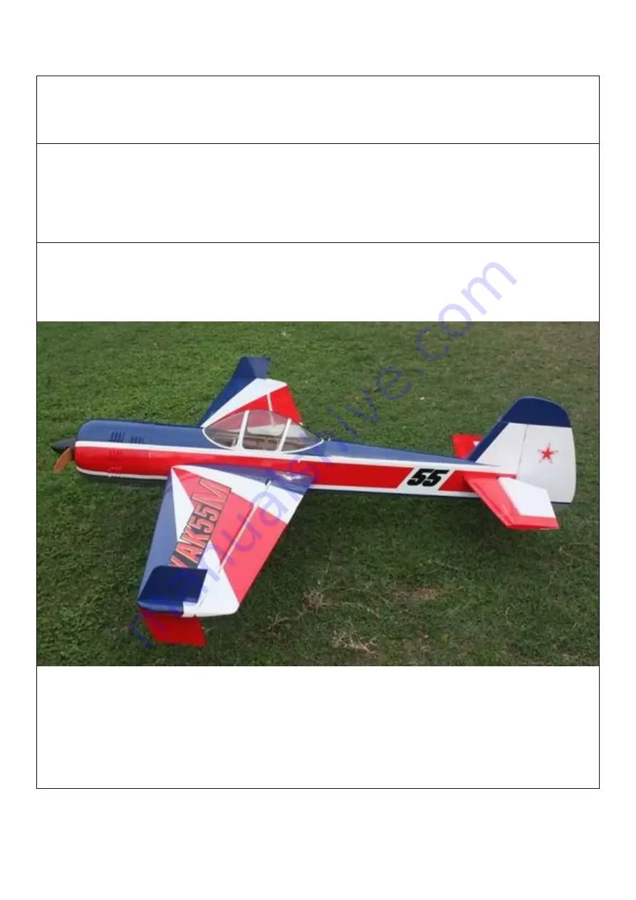
YAK55M 30CC
Giant Scale Aerobatic Aircraft
Page 1: ...GOLDWING RC YAK55M 30CC Giant Scale Aerobatic Aircraft...
Page 2: ...ntrol aircraft like any hobby or sport there are certain risks The operator of these models is responsible for these risks If misused or abused you may cause serious bodily injury and or damage to pro...
Page 3: ...the act of using the final assembled model the user accepts all resulting liability If you should find any missing or damaged parts or have any questions about this product please contact within 30 da...
Page 4: ...Side force generators Canopy hatch pins are made of nylon rods for better resistance aganist vibration Carbon Fiber accessories version Extra strength carbon fiber control horns...
Page 5: ...ed carbon fiber landing gear Carbon fiber tail wheel assembly with CNC machined metal parts including the aluminium tail wheel hub Increased diameter carbon fiber wing tube over previous versions Sche...
Page 6: ...Scheme E Yellow black red...
Page 7: ...of 160 in oz or better Appropriate servo arms for the above Servo wire extensions Recommend KUZA Twisted 22 AWG Servo Extensions Not included One 12 305mm No KAG002522 Three to four 18 455mm No KAG002...
Page 8: ...e it is secure to the airframe and other covering Be careful not to apply too much heat or you may cause bubbles or damage to the covering A heat gun may also be used along with a soft cotton cloth to...
Page 9: ...that will be glued to help adhesion KUZA new 360cc fuel Tank with alloy cap Push rod kits Two 2 5x60mm Pushrods for aileron Two 2 5x110mm Pushrods for elevator Ball link assembly Bag No KAG00122 8 for...
Page 10: ...Alu long arm kits 4 single arms for ailerons and elevator and rudder Servo lead safety clips 5 pcs Bag No KAG0021 Alu Main wheels 2pcs Bag No KAG0157...
Page 11: ...New axle kits Bag No KA03CH Carbon fibre tail wheel assembly with CNC machined metal parts including the aluminium tail wheel hub Bag No KAGC103 Extra covering provided for small repairs...
Page 12: ...4 allen key wrench Bag No KA03CE Side force generators 2 x 3x12mm hex bolts 2 x 3mm stainless steel self locking nuts 2 x washers Screews for landing gear 4 4x20mm hexagon bolts and 4 washers...
Page 13: ...RUDDER ASSEMBLY NOTE There are pictures of different planes in this manual however this plane s rudder is assembled the same way 1 It is much easier to install the twin control horns before installin...
Page 14: ...r slots Slide the control horns in place and make sure they are centered perfectly by using a ruler to measure between the pivot holes and the hinge line Wipe any excess glue off with isopropyl alcoho...
Page 15: ...age Using a fine drill pre drill the holes and drop thin CA into the holes to strengthen the wood You will need 3 inch arms on the servo Set up your radio accordingly and center the rudder servo 7 Alu...
Page 16: ...sition pinch the cable around the threaded coupler and then feed the loose end back through the brass tube Loop the cable back through the brass tube as before and crimp the brass tube three times jus...
Page 17: ...separately for rudder control LANDING GEAR ASSEMBLY NOTE There are pictures of different planes in this manual however this plane s landing gear is assembled the same way 1 Locate the supplied main a...
Page 18: ...axles to the composite landing gear and tighten the nylon insert lock nut Install one wheel collar onto the axle Use a second wheel collar as a guide to leave a gap on the inboard of the axle Use a sm...
Page 19: ...5 Fit the wheel pant in place and install using the two supplied screws Use thread lock to secure the screws in place Repeat the above steps for the other main gear...
Page 20: ...he accessories see the below picture 7 Line up the caron fiber assembly onto the body of the aircrtaft and use the holes as a drill guide Use a 2mm drill bit as a pilot hole then apply thin CA to hard...
Page 21: ...d apply thin CA It needs to be in a position where the spring is tensioned Use a self tapping screw to secure in place 9 The below is a picture of correctly installed tail wheel assembly NOTE One spar...
Page 22: ...ings is assembled the same way 1 Aileron push rod linkage set 2 The aileron control surfaces is Pre hingeds Locate the slots for the aileron control horn and remove the covering with a sharp knife Pla...
Page 23: ...the horn and plate into the aileron 5 Screw holes for servo mounting are pre drilled by laser in factory install servo with 4 self threading screws Fit a metal servo arm centering with your radio 6 L...
Page 24: ...t on the pushrod one end is reverse threaded Use M2 5 screws and nuts to connect the pushrod Set it so the aileron it level when the arm is at 90 degrees REPEAT FOR THE OTHER SIDE 8 We recommend using...
Page 25: ...nt planes in this manual however this plane s elevator is assembled the same way 1 Push rod linkage set for elevator 2 Find the slots for the control arms in the elevators and remove the covering wher...
Page 26: ...E OTHER SIDE 5 Locate the horizontal stabilizer use a hobby knife to remove the covering over the area that will be glued to fuselage It is essential that this is checked for alignment Place the wing...
Page 27: ...6 Place long arms onto the servo s you are planning to use for the elevators...
Page 28: ...he elevator If using one servo the 2 parts of the elevator need to be connected by the fiberglass block with glue as shown below The picture is for illustration only The connection of the 2 parts need...
Page 29: ...ngine Installation NOTE There are pictures of different planes in this manual however this plane s engine is assembled the same way 1 Select the correct guide for your engine and drill the holes and c...
Page 30: ...e securely using bolts washers and locknuts The use of thread lock is also highly essential for the engine bolts 3 Mount the ignition module according to the manufacturer s instructions The best place...
Page 31: ...linkage can be used 7 The KUZA new 360cc fuel tank is preassembled Complete the installation in the fuselage using zip ties or velcro straps to hold the tank in position Connect a fuel line between th...
Page 32: ...June 2015 and on all Goldwing gas airplanes are made ready for KUZA fuel dot and vent line plug Available in three colors black red and blue 2 Installation of KUZA CNC Aluminum Fuel Dot Sites for KUZA...
Page 33: ...Secure the housing of fuel dot with supplied 2 5 mm self tapping screws then plug and install the fuel line to complete the setup of fuel dot...
Page 34: ...lug installation are available at the bottom of the fuselage Secure KUZA vent line plug with four 2 5 mm self tapping screws as shown below Motor Installation 1 This YAK55M can also be flied with brus...
Page 35: ...firewall Then install the motor Adjust the motor mount to fit the cowl 4 After adjusting the motor mount to the right position lock the 4 screews unscreew them apply 30 minute epoxy and tighten the s...
Page 36: ...ere are pictures of different planes in this manual however this plane s cowling is assembled the same way 1 The cowl is secured with four 3 X 14mm bolts and washers Apply nutlock onto the bolts as th...
Page 37: ...dio installation and care is vital to the safe and reliable operation of your aircraft Follow the manufacturer s instruction for installation guidance of receivers and batteries paying attention to fa...
Page 38: ...127 137mm 5 5 4 inches behind the leading edge of the wing at the root More experienced pilots may want to set the CG further aft for more 3D capability Varying weights of engines and radio gear will...
Page 39: ...el tank making sure your vent line is not plugged or capped With the canopy off this is a good time to check for any fuel leaks 5 Check all control surfaces for secure hinges by performed a slight tug...
Page 40: ...w ready for your maiden flight Good luck and enjoy your new aircraft If you have any comments or questions about this manual or the aircraft please email service goldwingrc com Recommend Accessories N...
Page 41: ...el Dot 3 color to choose black blue red No KAG0231B or KAG0231U or KAG0231R KUZA CNC Aluminum Fuel Vent Line Plug 3 color to choose black blue red No KAG0232B or KAG0232U or KAG0232R KUZA Fuel line cl...
Page 42: ...KUZA Heavy duty 7075 aluminum Servo Arm For Futaba servo 25T 39mm 1 5in Single No KAG0S72F For Hitec servo 24T 39mm 1 5in Single No KAG0S72H For JR servo 23T 39mm 1 5in Single No KAG0S72J...
Page 43: ...KUZA new Wingbag for 73in SBACH Two color to choose red black blue silver No KAG0093 GOLDWING RC www goldwingrc com...