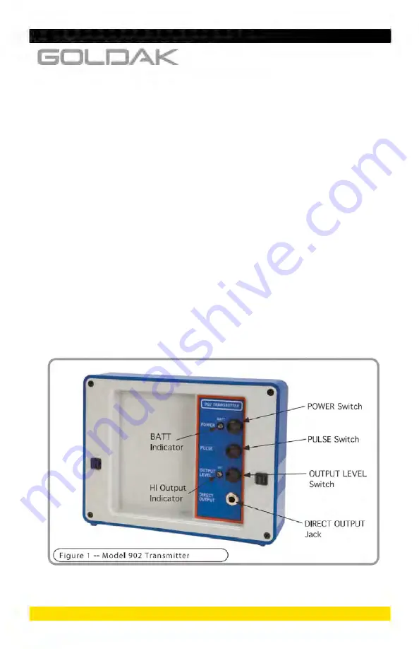
cable to the line to be traced. Section D of this manual,
“Operating Procedures,” explains these transmission meth-
ods in greater detail. A detailed explanation of the transmitter
features and controls follows here
(refer to Fig. 1)
:
a) The
POWER
Switch. This booted push-button switch
controls the power state of the transmitter. Depressing
this switch so that the adjacent “BATT” light illuminates
“turns on” the transmitter, causing it to generate a signal.
Depressing the switch again will deactivate the transmit-
ter.
b) The
BATT
Indicator. This LED is lit when the transmitter is
activated and the condition of the battery source is good.
If this LED does not illuminate when the POWER switch is
pressed, or it becomes unlit during operation, the batter-
ies need to be replaced.
2


