17
Electric Controls
Optional electric controllers allow for on/
off switching of individual boom sections via
boom valves, as well as a pressure adjustment
toggle to increase or decrease the operating
pressure of the boom.
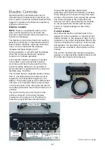
Geoline console
NOTE:
There is a redundant switch on the
early control boxes that is not wired into
any valve, and therefore does not perform a
function at this stage.
The Geoline control panel has boom section
switches (control box comes standard with 4
boom section switches, although commonly
only 2 or 3 are used) and the pressure
increase/decrease toggle switch.
During operation, a red LED light illuminates
when the corresponding boom switch is
turned on to indicate operation.
It is important that the console is mounted
in the cabin in such a way that it cannot
work loose and become a projectile in the
event of sudden braking or an accident. A
swivel bracket is supplied with the console to
facilitate easy mounting.
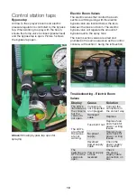
The console has two separate cables coming
from it, one being the power cable which is
required to be connected straight to a 12V
battery. The positive power wire is fitted with a
10A fuse. It is important that this fuse remain
in the wiring loom when wiring into the tractor
as a safety protection fuse for both tractor and
console.
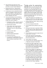
The second wiring loom coming from the
console connects to the wiring harness
mounted on the sprayer. It is important to
route the sprayer harness into the tractor
through the appropriate rubber cabin
grommets, and ensure the harness is located
firmly. Bringing the harness through the back
window of the tractor, then closing the window
can cause damage to the wires within the
harness over time. Also allowing the harness
to rub alongside the drivers seat has been
known to cause breakages in the wiring
harness.
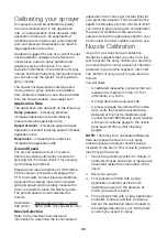
Control station
As well as the electric controls fitted to the
sprayer for boom operation, a manual control
station remains on the sprayer to allow for the
operation of any other accessories fitted to the
machine including the hose reel, venturi probe
and agitator. The operation of the probe and
hose reel are covered in other sections of the
manual.
The control manifold also features 2 pressure
gauges, one representing bypass pressure and
the other boom spray line pressure.
Pressure
+/-
toggle
Boom section
switches
Redundant
switch
(not used)
Master
ON/OFF
Swivel bracket
Continued over page


