background image

STE5 Operation Manual 
 

32

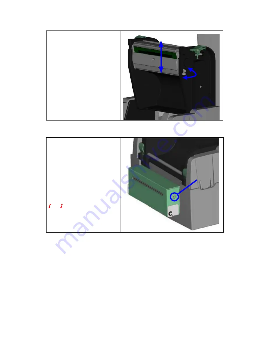
6-3. Print Line Adjustment 

To get better printing balance and 
quality, use print head adjusting gear 
to adjust the contacting surface 
between print head and label. 
 
1. 

When turning print head 
adjusting gear counter-clockwise 
(as arrow 1 shows), print head 
would move in the direction 
where arrow A shows. 

 
2. 

When turning print head 
adjusting gear clockwise (as 
arrow 2 shows), print head 
would move in the direction 
where arrow B shows. 


A

B

1

2


6-4. Adjust the cutter 

1. 

A cutter-adjusting hole is present 
on the side of cutter (where A is 
pointing to). 

 
2. 

The cutter will not work properly if 
there is a paper jam. Turn the 
power off and use a #M3 hexagon 
wrench inserted into hole “A”, and 
then turn it counter-clockwise. 

 
3. 

Power on the printer after clearing 
the paper jam, the cutter will reset 
automatically. 


Note


The label / paper used for cutting is 
suggested to be at least 30mm in   
height. 

A


Summary of Contents for STE5

Page 1: ...P N 920 013911 00 Rev D 03 2013 ...

Page 2: ...on Manual 1 CAUTION Danger of explosion if battery is incorrectly replaced Replace only with the equivalent type recommended by the manufacture Dispose of used batteries according to the manufacturer s instructions ...

Page 3: ...ollte versehentlich Flüssigkeit in das Gerät gelangen so ziehen sofort den Netzstecker Anderenfalls besteht die Gefahr eines lebensgefährlichen elektrischen Schlags 5 Wartungs und Reparaturarbeiten dürfen aus Sicherheitsgründen nur von autorisierten Personen durchgeführt werden 6 Bei Wartungs und Reparaturarbeiten müssen die Sicherheitsvorschriften der zuständigen Berufsverbände und Behörden unbed...

Page 4: ...power source to prevent possible transient over voltage damage 4 Don t pour any liquid to the equipment to avoid electrical shock 5 ONLY qualified service personnel for safety reason should open equipment 6 Don t repair or adjust energized equipment alone under any circumstances Someone capable of providing first aid must always be present for your safety 7 Always obtain first aid or medical atten...

Page 5: ...tion 15 2 5 PC Connection 15 3 PRINTER SETTING 16 3 1 FEED Key 16 3 2 LED Status 16 3 3 Auto Sensing 16 3 4 Self Test page 17 3 5 Error Messages 18 4 RFID TAG ENCODING 19 4 1 Install and Register Smart Media Manager 19 4 2 RFID Tag Encoding 22 4 3 RFID Utilities 25 4 4 RFID Messages 27 5 ACCESSORY 28 5 1 Stripper Module Installation 28 6 Maintenance and Adjustment 31 6 1 Thermal Print Head Cleanin...

Page 6: ...s Model STE5 Print Method Thermal Transfer Direct Thermal Resolution 203 dpi 8 dot mm Print Speed 4 IPS 100 mm s Print Width 4 25 108 mm Print Length Min 0 39 10 mm Max 68 1727 mm Memory 4MB Flash 2MB for user storage 8MB SDRAM Sensor Type Adjustable reflective sensor Fixed transmissive sensor central aligned Ribbon Types Wax wax resin resin Length 981 300 m Width 1 18 Min 4 33 30 mm 110 mm Max Ri...

Page 7: ...ownloadable from the software Interfaces Serial port RS 232 DB 9 USB port default on Parallel port Centronics 36 pin Control Panel Two bi color status LEDs Ready Status Control key FEED Power Auto Switching 100 240VAC 50 60Hz Environment Operation temperature 41 F to 104 F 5 C to 40 C Storage temperature 4 F to 122 F 20 C to 50 C Humidity Operation 30 85 non condensing Storage 10 90 non condensing...

Page 8: ... Initialize Error Signal Ground N C Select in host printer host printer printer printer printer host printer host host printer printer host printer Serial Interface Serial Default Setting 9600 baud rate no parity 8 data bits 1 stop bit XON XOFF protocol and RTS CTS RS232 HOUSING 9 pin to 9 pin DB9 SOCKET DB9 PLUG 1 1 5V max 500mA RXD 2 2 TXD TXD 3 3 RXD DTR 4 4 N C GND 5 5 GND DSR 6 6 RTS RTS 7 7 ...

Page 9: ...op Cover 3 Label Roll Core 4 Ribbon Rewind Wheel 5 Print Mechanism 6 Ribbon Rewind Shaft Empty Ribbon Roll 7 Locking Tenon left right 8 Front Cover Piece 2 1 3 4 5 1 LED Light Ready 2 LED Light Status 3 FEED Key 4 CF Card Slot Cover 5 Print Head Pressure Adjustment Screw left right ...

Page 10: ...Guide 3 Platen Roller 4 Print Line Adjustment Gear 5 Label Sensor 1 2 5 4 6 7 3 1 Fan Fold Label Insert 2 Power Switch 3 Ethernet Socket Option 4 USB Port 5 Parallel Port 6 Serial Port RS 232 7 Power Socket The communication ports may vary depending on product types ...

Page 11: ...s necessary it only requires direct thermal media Please check which print mode you will use and then go into the Setting Mode to change the print mode setting if necessary 2 1 Ribbon Installation 1 Place the printer on a horizontal surface and open the top cover by pressing the Cover Open Buttons on both sides 2 Loosen and then lift the upper print mechanism by pressing the locking tenons 3 Place...

Page 12: ...n Manual 11 4 Feed the ribbon from the Ribbon Supply Shaft under the Print Head 5 Wrap the ribbon around the Ribbon Shaft and stick the ribbon onto the Empty Ribbon Roll Core 6 Firmly close the upper print mechanism ...

Page 13: ...both sides 2 Insert the Label Roll Core into the label roll and then place it into the printer 3 If it s necessary you can also assemble the Label Stop Plates on both sides of label roll Without Label Stop Plate With Label Stop Plate 4 Loosen and lift the upper print mechanism by pressing the locking tenons ...

Page 14: ... Operation Manual 13 5 Feed the label through the two Label Guides to the Tear off Bar 6 Align the label guides to the label edge 7 Close the upper print mechanism from the top to finish label installation ...

Page 15: ...STE5 Operation Manual 14 2 3 Label Roll Core Installation Instruction A 1 roll core installation B 1 5 roll core installation C 3 roll core installation ...

Page 16: ...Tag hole position Sensor Detection Position Sensor 2 5 PC Connection 1 Please make sure the printer is powered off 2 Take the power cable plug the cable switch to the power socket and then connect the other end of the cable to the printer power socket 3 Connect the cable to the USB parallel port on the printer and on the PC 4 Power on the PC and the printer and the printer s LED light will shine ...

Page 17: ...s and hold the FEED Key then power on the printer READY Red Flash 3 Auto Sensing Mode Printers are currently in Auto Sensing Mode The calibration will be performed and a Self Test page will be printed out to show the configurations of printer For more detail about Auto Sensing Mode please refer to next section For the descriptions of Self Test page please refer to page 17 STATUS Orange 3 3 Auto Se...

Page 18: ...ONT S IN MEMORY 000 ASIAN FONT S IN MEMORY 000 DATABASE S IN MEMORY 000 TTF S IN MEMORY 2048K BYTES FREE MEMORY S4 H10 R000 R200 W10 Q48 3 Option D0 O0 AD Reflective Sensor AD 639 754 928 10 Code Page 850 Model Version Serial port setup USB port setting Test pattern Number of DRAM installed Image buffer size Number of forms Number of graphics Number of fonts Number of Asian fonts Number of Databas...

Page 19: ...nable to detect paper Make sure the movable sensor mark is at the correct position if the sensor is still unable to detect paper and then go through Auto Sensing again Paper used up Replace with new label roll Red 2 beeps twice Abnormal paper feed Possible causes card tags or paper fall into the gap behind the platen roller can t find label gap black mark black mark paper out Please adjust it acco...

Page 20: ...FID tag encoding you should register the SMM first and then perform the encoding and printing through the SMM Please note that SMM is the only tool to make STE5 printing or encoding 4 1 Install and Register Smart Media Manager 1 Insert the product CD into PC s optical driver 2 On the user interface of product CD click the installation link to start the installation Or you can open the file directo...

Page 21: ...k the New icon on the up left corner of program window to create a new label file 8 Complete label and printer settings and click the OK button A pop up window will be showed and ask you to enter the Security Code Note please refer to SMM Operation Manual for more details about using and setting of SMM 9 Enter the Security Code on registration window and then click the OK button ...

Page 22: ...ile should be matched to each other and can t be used separately 12 After SMM has been registered you can start to register STE5 printer now 13 Please open the registration window from SMM s menu bar and enter the same Security code to register STE5 printer Note 1 All SMM functions will be disabled before the registration is completed 2 For security reason you still need to enter the Security Code...

Page 23: ...oad the Smart Label properly on STE5 2 Press the New Label icon on SMM tool bar to start editing a new label 3 Press the Printer Font icon on SMM tool bar a Printer Font setting page will pop up 4 Tick the RFID option on Printer Font setting page then the Printer Font entry area will switch to RFID entry fields ...

Page 24: ...ress OK button on the Printer Font setting page when all RFID entry fields are filled A RFID icon will appear on the label editing page to show the data content in RFID tag 7 If you need to print readable content with printer font on Smart Label just tick the Enable Print option and fill in the content you want to print then press OK button ...

Page 25: ... completed 9 On Label Printer Setup page you can change label and printer settings accordingly Press the Print button and the printer will encode RFID tag and print out readable content at the same time 10 When sticking a programmed Smart Label on a new label core the Smart Label should be parallel to the label core as the figure showed ...

Page 26: ...utility will check if the module still works properly RFID tag Reading Utility 1 Load the Smart Label properly on STE5 2 Select the Read Tag Infor function from advanced functions on SMM 3 Press the Read button on the bottom of RFID Tag Info display page The printer will start to read the data that has been encoded in RFID tag and list the data on corresponding data fields Hence you can use this f...

Page 27: ...hanism of printer 2 Put a Smart Label on the place that is marked with red circle in figure This is the place where the RFID module is embedded 3 Select the RFID Module Check function from advanced functions on SMM The printer will then keep beeping if RFID module works well 4 To leave from RFID Module Checking mode jut press the FEED key on printer ...

Page 28: ...oding the RFID tag Tag Invalid The message will appear when encoding with RFID tag which is not provided by Godex Please change to right one Communication Fail There may be some problems on data transmission between printer and PC Please make sure the printer is connected with PC through USB port the message FAIL is printed out on Smart Label The process of RFID encoding failed because error occur...

Page 29: ...er by pressing the Cover Open Buttons on both sides 2 Loosen and then lift the upper print mechanism by pressing the locking tenons 3 Unlock the front cover piece by pushing locks inward 4 Lift take off the front cover piece according to the direction shown in the figure 5 Plug in the stripper connector onto the switchboard socket refer to right figure Note There are 2 sockets on the converting bo...

Page 30: ...hrough the Label Guides Note The label paper used for stripper is suggested to be at least 25mm in height Suggestion When printing with stripper module it is suggested to set the stop position E to 9 9 Peel off the first label and feed the liner through the roller and the Tear off Bar 10 Follow the direction as shown in figure to feed the liner across the stripper ...

Page 31: ...STE5 Operation Manual 30 11 Close the upper print mechanism and the stripper 12 Press the FEED key to adjust the position of label and complete the installation ...

Page 32: ...ng tenons 4 If on the print head see blue arrow there s label pieces or other stain please use a soft cloth with industrial use alcohol to wipe away the stain Note1 Weekly cleaning on the print head is recommended Note2 When cleaning the print head with soft cloth make sure there is no any metal or hard particles attached on it 6 2 Thermal Print Head Balance Adjustment When printing with different...

Page 33: ... adjusting gear clockwise as arrow 2 shows print head would move in the direction where arrow B shows A B 1 2 6 4 Adjust the cutter 1 A cutter adjusting hole is present on the side of cutter where A is pointing to 2 The cutter will not work properly if there is a paper jam Turn the power off and use a M3 hexagon wrench inserted into hole A and then turn it counter clockwise 3 Power on the printer ...

Page 34: ...s creating friction with the platen roller If the platen roller needs to be replaced please contact your reseller for more information Check if power supply is correct When printing part of the label wasn t printed completely Check if Thermal Print Head is stained or dusted Use internal command T to check Thermal Print Head can print completely Check the media quality Printout not in desired posit...

Page 35: ......

Reviews: