1 0991 483
EN
-
21.12.2011
NGV A3
VALVE
M
ANUAL
I
NSTALLATION
, U
SE AND
M
AINTENANCE
41 / 46
1.05
ENG
Motor protection functionality
-
Disconnect one terminal of the thermistors, and check that the motor
protection working properly.
Filter
-
Check the main filter (FIL) mounted inside the silencer and clean it if is
necessary.
Pressures check
-
Check static and dynamic (working) pressure at the end of installation.
Check regularly that all values of these parameters remain unchanged.
Pressure gauge shut off (4)
-
Close the ball valve (B), open the pressure gauge shut off (4) and fully discharge the pressure using
electro-valve (VMD). Close the pressure gauge shut off (4) open the ball valve (B) and check that the
level shown on pressure gauge is zero.
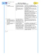
Pressure test (static pressure x2)
·
This test assures you about the integrity of parts under pressure, including those which can not be visually
checked.
·
To correctly carry out this test follow these instructions and make reference to the images:
-
Close the pressure gauge valve (4).
-
Close the ball valve (B). Remove the pressure gauge (MAN).
-
Connect the hand pump (M) in place of the pressure gauge (G1/4) as
shown in the image on the right side
-
Open the pressure gauge valve (4).
-
Open the ball valve (B).
-
Open the hand pump valve (N) for about 1 minute.
-
Close the hand pump valve (N).
-
Close the ball valve (B).
-
Operate the hand pump (M) until the required pressure is reached,
checking it on hand pump pressure gauge (O).
-
At the end of the test, discharge the pressure to zero by pressing the
push-button on (VMD) (see image up).
-
Close the pressure gauge shut off (4).
-
Disconnect the hand pump (M)
-
Mount the pressure gauge (MAN).
Ball valve seal
-
Close the ball valve (B) and open the pressure gauge shut off (4). Fully
discharge the pressure-using valve (VMD). check that the level shown
on pressure gauge (MAN) is zero.
LEGEND:
M – Test hand pump
N – Shut off valve for H-pump
O – Pump pressure gauge
P – Pump fitting
Q – Cupper washer
Labels, signs and schemes
-
Check that all the tags and diagrams are in place and legible (oil data label, emergency operation
manual, electrical diagram and hydraulic power unit schemes).
Overall check-up
-
Perform an overall check up of the power unit. When the overall check-up ends, check all the settings
for the power unit start-up.
·
Replace or restore all the components not correctly working
.
NOTE
In case of oil replacement, do not throw the oil away in the environment, but give it to oil recycling
company.
NOTE
When the power unit in no longer required, don’t throw it away, but give it to a recycling company or to
the manufacturer.
¥
"
Summary of Contents for NGV A3
Page 47: ... ...


