1 0991 483
EN
-
21.12.2011
NGV A3
VALVE
M
ANUAL
I
NSTALLATION
, U
SE AND
M
AINTENANCE
35 / 46
1.05
ENG
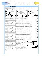
- 5 - SETTINGS
Data entered by GMV, run control during the installation of the system
NGV VER XX.XXX
5-SETTINGS
Ý
Þ
5.1 LIFT RATIO
X:X
Ratio of the lift system (1:1; 2:1; 3:1)
Ý
Þ
5.2 JACK DIAM.
XXX mm
Diameter or correspondent diameter of the jack [mm]
(see data on technical catalogue tables)
Ý
Þ
5.3 PUMP FLOW
XXX l/min
Flow rate of the pump [l/min]
Ý
Þ
5.4 MAP
XXXX
Map code of the power unit (not active)
Ý
Þ
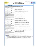
5.5 PSTAT MIN
XX.X bar
Minimum static pressure (5.0 ÷ 45.0 bar)
Ý
Þ
5.6 PSTAT MAX
XX.X bar
Maximum static pressure (Pstat Min. ÷ 45.0 bar)
Ý
Þ
5.7 P MIN
XX.X bar
Minimum pressure (1.0 ÷ 10.0 bar) medium value ±5 bar
Ý
Þ
5.8 P FULL LOAD
XX.X bar
Full load pressure, 80% of nominal load (12.0 ÷ 45.0 bar)*
Ý
Þ
5.9 P OVERLOAD
XX.X bar
Overload pressure, 110% of nominal load (12.0 ÷ 50.0 bar)*
Ý
Þ
5.10 P MAX
XX.X bar
Pressione di massima, 140% del carico nominale (15.0 ÷ 70.0 bar)*
Ý
Þ
* Re-calculated value when the P
stat,MIN
value (parameter 5.5) or the
P
stat,MAX
value (parameter 5.6) are modified
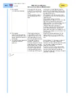
5.11 COOL TEMP.
XX °C
Maximum allowable fluid temperature
(5.0 ÷ 70.0 °C) set value 70°C
Ý
Þ
5.12 MODE:
XX - XX
Mode: NORMAL Mode:INSTALLATION
NOTE
If the mode set is : NORMAL, the valve works as shown into the manual.
If the mode set is : INSTALLATION, the valve works at V2 speed regardless of signal it receives from
the control panel. The installation mode is used routinely during the installation of the system.
¥
"
Summary of Contents for NGV A3
Page 47: ... ...


