background image


GMV SPA


FLUID DYNAMICS EQUIPMENTS AND 
COMPONENTS FOR LIFTS 


UNI EN ISO 9001 
Certified Company 


1.01 

ENG 


English 

   


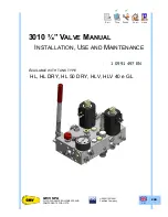
3010 ¾” VALVE 


S

ELL


T

ECH


W

ORK


C

UST


U

SER


3010


¾”


V

ALVE 

M

ANUAL


I

NSTALLATION

,


U

SE AND 

M

AINTENANCE


1 0991 497 EN 


A

VAILABLE WITH TANK TYPE


HL, HL DRY, HL 50 DRY, HLV, HLV 40 e GL 


Summary of Contents for 3010

Page 1: ...ND COMPONENTS FOR LIFTS UNI EN ISO 9001 Certified Company 1 01 ENG English 3010 VALVE SELL TECH WORK CUST USER 3010 VALVE MANUAL INSTALLATION USE AND MAINTENANCE 1 0991 497 EN AVAILABLE WITH TANK TYPE HL HL DRY HL 50 DRY HLV HLV 40 e GL ...

Page 2: ...3 3 ADJUSTMENT OF THE UPWARD ACCELERATION N 4 10 3 4 ADJUSTMENT OF SLOW LEVELLING SPEED N 2 10 3 5 ADJUSTMENT OF THE UPWARD HIGH SPEED N 8 10 3 6 ADJUSTMENT OF THE DOWNWARD ACCELERATION N 7 10 3 7 ADJUSTMENT OF THE DOWNWARD HIGH SPEED N 9 10 3 8 ADJUSTMENT OF THE UPWARD AND DOWNWARD DECELERATION N 3 10 3 9 PIPE RUPTURE VALVE VC TEST IN THE VALVE BLOCK N 5 11 3 10 ADJUSTMENT OF THE MINIMUM RAM PRES...

Page 3: ...ressure adjustment 7 Downward start adjustment 8 High speed adjustment 9 Down speed compensator empty full load 10 Hand pump max pressure adjustment 11 Minimum upward pressure adjustment RUB Shut off valve for pressure gauge exclusion MAN Pressure gauge MM Manual lowering button PAM Hand pump V Hand pump air purge screw VP Pilot valve CHK Check valve VMD Downward solenoid valve VML Jump speed sole...

Page 4: ...the documentation shouldn t be damaged and shouldn t have missing parts Moreover do not tear or deteriorate sheets during consulting 0 3 SAFETY PRECAUTION DURING INSTALLATION WARNING Before starting all kind of installation operation ALWAYS verify that all the safety devices mechanical or electrical are active and working properly 0 4 TOOLING Use standard building yard tooling for the installation...

Page 5: ...LATION In these instructions the major points concerning the safety and prevention will be marked with the following symbols General warning Warning high risk of danger Risk of injury e g crushing sharp edges protrusions etc Warning risk of electrical damage exposed parts Beyond the instruction manual it should take into account national standards laws regulations and other rules on accident preve...

Page 6: ...ting the different working procedures and therefore do not take any action without first considering the consequences Make sure that the products received are complete with everything you need and that all products and parts are not damaged during transport Data written on the label should be compared with the order form During the storage period keep the material in the original container protect...

Page 7: ...Screw for rupture valve test EN 81 20 6 Minimum ram pressure adjustment 7 Downward start adjustment 8 High speed adjustment 9 Down speed compensator empty full load 10 Hand pump max pressure adjustment 11 Minimum upward pressure adjustment RUB Shut off valve for pressure gauge exclusion MAN Pressure gauge MM Manual lowering button PAM Hand pump V Hand pump air purge screw VP Pilot valve CHK Check ...

Page 8: ... all electrical power by opening the main switch Power wires must be of sufficient section to support the required current and appropriate insulation for the voltage of the mains Wires must not come in contact with hot parts The ground wire should always be connected to the screw marked with the appropriate symbol 2 6 CONNECTION BOX Power units with immersed motor have the motor connection box loc...

Page 9: ...de the pipe as this may cause a damage to the gaskets seals of the piston and the valves jeopardising the correct functionality of the system Remove the nut and the compression fitting ring from the silencer joint Insert the compression fitting ring as shown in the figure Make sure that the silencer joint is tight Clean and apply a thin layer of oil to the thread and the joint area Insert the tube...

Page 10: ...DJUSTMENT OF THE UPWARD HIGH SPEED N 8 Start to send the car upward Loosen the lock nut 8 Tighten the screw 8 till you hear the oil returning to the tank then loosen one turn to close Tighten the lock nut 8 The adjustment is finished If needed in those lifts where the speed must be limited for example Home Lift con V 0 15 m s other lifts just gradually tighten the screw 8 to mach the requested spe...

Page 11: ...ADJUSTMENT OF THE MINIMUM RAM PRESSURE VSMA 2 1 SYSTEMS N 6 Only in installations with traction 2 1 Close the ball valve S Press the manual lowering button MM to release pressure Check the pressure on the manometer MAN is around 6 bar If the pressure it not correct adjust screw 6 The adjustment is finished 3 11 MANUAL LOWERING OPERATION EMERGENCY ONLY BUTTON MM Press the manual lowering button MM ...

Page 12: ... of the oil 6 Motor protection operation 6 Filters 1 Pressure check 6 Pressure gauge shut off 6 6 Pressure test static pressure x2 6 Ball valve seal 6 Labels signs and schemes 6 Overall check up 5 4 3 MAINTENANCE OPERATIONS What to do Valve gaskets seals At the end of installation and during check ups verify the gasket seals in the following way with the oil at room temperature close the ball valv...

Page 13: ...se the ball valve S again Continuing with the hand pump reach the desired pressure value controlling with the pressure gauge After the test completely unload the pressure pushing with a screwdriver on the VMD valve Close the pressure gauge exclusion valve Disconnect the hand pump Screw the pressure gauge MAN Ball valve seal Close the ball valve S and open the pressure gauge shut off RUB Fully disc...

Page 14: ...ward speed is less than the upward speed DEVICES VRF VMD COMPENSATOR VRF Check the adjustment of the screw 8 VMD Check the cleanliness of filters and restrictors SPEED COMPENSATOR Check the perfect sliding of the spool If it s necessary tighten the screw 9 to increase downwards speed The lift only runs at high speed both upward and downward DEVICES VML VRF VML Check that the screw 3 is open Clean ...

Page 15: ...ENG 1 01 1 0991 497 EN 24 03 2017 15 16 3010 VALVE MANUAL INSTALLATION USE AND MAINTENANCE ...

Page 16: ...NCE 16 16 Doc n 1 0991 497 Rev 1 00 24 03 2017 File 3010 3_4_10991497EN doc FLUID DYNAMICS EQUIPMENTS AND COMPONENTS FOR LIFTS UNI EN ISO 9001 Certified Company GMV SPA Via Don Gnocchi 10 20016 PERO Milano Italy TEL 39 02 33930 1 FAX 39 02 3390379 http www gmv it e mail info gmv it ...

Reviews: