background image

3


1. 


General Information


The Level Wind is a chain driven device specifically designed to distribute wire rope coils or 

wraps evenly across the winch drum.


Level winding the wire rope onto the drum has several advantages:


●  

Increases drum storage capacity.


●  

Prevents wire rope pileup.


●  

Permits smooth, steady pulls.


●  

Establishes tight, even wraps preventing the wire rope from cutting down through the lower 

lays resulting in damage to the rope and difficulty in unwinding.


2. 


Description


The level wind assembly includes a carriage/roller cage, guide bars, speed reducer, two single 

width and one triple width roller chain drive.


The carriage is mounted on two guide bars and is driven side to side across the drum by an end-

less triple width cross chain (

See Figure 1 on page 2

).


The carriage is connected to the cross chain by a drive pin which projects into a vertical slot in 

the carriage. As the cross chain rotates, it carries the drive pin and the carriage across the drum. 

When the drive pin reaches the end sprocket, it rotates around the sprocket moving up or down 

in the slot as required. Accordingly, the carriage and wire rope moves to the end of its travel and 

starts back again across the drum.


Positioned above the carriage (or below in the under wind configuration) is the roller cage as-

sembly thru which the wire rope passes for final storage on the drum. The rollers are shielded 

with a roller guard for the purpose of operational safety.


3. 


Operation


The level wind is mechanically driven from the motion of the winch drum. Use caution to maintain 

uniformity and compactness of the wraps and lays of the wire rope on the drum at the start of the 

pull.


The carriage remains properly aligned because the level wind is mechanically driven directly 
from the winch drum. This is true of whether the rope is paying onto the drum under power or 
paying out under free spool conditions.


The speed of the carriage is regulated. For each revolution of the winch drum, the carriage ad-
vances across the drum a distance equal to the diameter of the rope.


Initially, the correct sprockets are determined by the factory relative to the nominal cable size 
that is specified for the winch. Due to minor variations in the diameter of the wire rope, the aver-
age diameter may have to be determined in order to modify the speed of the rope winder. Take 
several diameter measurements along the length of the wire rope, and call GMP to determine 
the correct sprocket combination. 


Once a given set of sprockets has been established for a specific wire rope diameter, the rope 
diameter cannot be changed without a change in the sprocket teeth combination.


Constant tension must be maintained on the rope when operating the level wind. 

The 

amount of tension should be sufficient to eliminate 

clock springing

” 

that will lead to loose or tan-

gled wraps and lays.


Under free spool conditions, if the drum has been permitted to over

-

run, resulting in loose or tan-

Summary of Contents for Adams CD3

Page 1: ...d reproduced or transmitted in any form whatsoever without the written permission of General Machine Products KT LLC Adams Model CD3 WG Rope Winder INSTALLATION OPERATION MAINTENANCE GMP 3111 Old Lincoln Hwy Trevose PA 19053 USA TEL 1 215 357 5500 FAX 1 215 357 6216 EMAIL www gmptools com July 17 2018 USA Ver 2a ...

Page 2: ...ON 3 4 0 PLACING WIRE ROPE ONTO THE WINCH DRUM 4 5 0 ADJUSTMENT 5 6 0 LUBRICATION 6 7 0 SPROCKET AND CHAIN SELECTION 6 8 0 WIRE ROPE 7 9 0 WIRE ROPE LUBRICATION 8 10 0 REPAIR PARTS 8 PARTS IDENTIFICATION DRAWING 9 PARTS LIST 10 11 REDUCER ASSEMBLY INDENTIFICATION 12 Cross Chain Carriage Roller Cage Guide Bars End Sprocket Speed Reducer Drive Pin Figure 1 Underwind Assembly Shown ...

Page 3: ...llers are shielded with a roller guard for the purpose of operational safety 3 Operation The level wind is mechanically driven from the motion of the winch drum Use caution to maintain uniformity and compactness of the wraps and lays of the wire rope on the drum at the start of the pull The carriage remains properly aligned because the level wind is mechanically driven directly from the winch drum...

Page 4: ...t a point to keep the spliced eye or quick hook several feet from the roller cage Otherwise the eye and hook will be drawn into the roller cage causing damage to the level wind If for any reason it is necessary to remove the wire rope from the roller cage while at a mid point in the rope it can be done by removing the roller cage top plate First remove the 2 hex bolts on the roller cage top plate ...

Page 5: ...ng a measurement at four locations to check for equal spacing Checking in four locations will compensate for any distortion in the drum flanges Shift the cross chain assembly by turning the adjusting screws at each end after the lock nuts have been loosened If the rope piles up at one end and leaves an opening at the other end shift the cross chain slightly away from the end where the rope piles u...

Page 6: ...E The WG winch is designed to accept 7 16 diameter wire rope only American produced wire rope is never smaller than the nominal diameter always larger with a plus tolerance of 1 32 in the size range used on GMP Adams Winches Some foreign product may be smaller Should synchronization difficulty be experienced with standard sprockets measure the diam eter of the wire rope in three locations with a m...

Page 7: ... Wire Rope 8 1 Spooling When installing the wire rope observe the following recommendations It is important to select the correct winch rope for a particular application Wire rope is specified by length diameter number of strands number of wires per strand type of center and type of lay The purpose is to stress the importance of selecting the correct type of lay There is a definite advantage in ap...

Page 8: ... direction of the lay of the rope given the direction of drum rotation When the drum will be under winding as the wire rope is spooled in use the rope clamp on the side of the drum which is opposite of the lay of the wire rope For example if using right lay rope on an under wind drum attach the wire rope to the left side rope clamp The wire rope must be guided and maintained as it is routed forwar...

Page 9: ...9 ...

Page 10: ...g Pin 1 14 16938 Cap Screw Hex Head 1 2 20 x 2 4 15 17591 Nut Hex 1 2 20 4 16 09324 1 2 Lock Washer SAE medium 5 17 17575 Nut Jam Steel 1 2 13 3 18 16762 Collar W Set Screw 1 19 15585 Bracket Assembly w Item 21 2 20 Same as item 19 21 16723 Bushing Oilite For Item 19 2 22 14949 14972 Sprocket w Set screw 40 Teeth for 7 16 1 2 wire rope Sprocket w Set screw 36 Teeth for 5 16 3 8 9 16 wire rope 1 23...

Page 11: ...procket 12 Teeth With Set Screw for 7 16 1 2 9 16 wire rope 1 16751 Key 1 4 Square x 1 Long 1 42 28818 26295 Cross Chain Guard 19 drum WG Cross Chain Guard drum CD3 1 43 28785 26132 Support Shaft Level wind Hanger Side WG Support Shaft Level wind Hanger Side CD3 2 2 44 14967 Second Reduction 5 8 Roller Chain 80 Pitches Includes Connection Link 1 45 16727 Cap Screw Hex Head 5 16 24 x Long 4 46 0504...

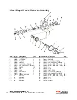
Page 12: ...earing 1 21 17140 Gasket Shim 005 blue AR 6 16033 Bolt Hex Hd 5 16 18x3 4 6 21 15980 Gasket Shim 020 yellow AR 7 15981 Gasket AR 22 16446 Cup 1 8 16445 Cup 2 23 16444 Cone 1 9 16443 Cone 2 24 15965 Shaft Worm 1 10 15977 Gear Worm 1 25 15973 Carrier Closed Bearing 1 11 15978 Key 1 26 16033 Bolt Hex Hd 5 16 18x3 4 4 12 15979 Shaft Worm Gear 1 27 17140 Gasket Shim 005 blue AR 13 xx Not used 27 15980 ...

Page 13: ...13 The GMP Limited Warranty can be found at http www gmptools com warranty ...

Page 14: ...ucts KT LLC 3111 Old Lincoln Highway Trevose PA 19053 USA TEL 215 357 5500 FAX 215 357 6216 E MAIL info GMPtools com WEB http www GMPtools com GMP reserves the right without notice to make changes in equipment design or components as progress in engineering or manufacturing methods may warrant All contents 2012 GMP ...

Reviews: