background image

G D 9 6 0 0   s E r i E s    

i n s t r u c t i o n   m A n uA l  

PA G E   7

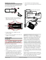
remoVINg the clear coVer

if your GD9600 will be mounted in a dry protected location 
away from the possibility of water ingress, the front clear 
cover can be permanently removed

1.  remove the 4 screws from the top and bottom inside 

edge of the mount frame as shown above. remove  
top latch assembly and clear cover..

2.   Fit replacement fill strips as supplied into top and  

bottom frame edges. 

3.   mount your unit into the bulkhead. use the screw caps 

supplied to cover screw heads. 

electrIcal WIrINg
dc connections

caution:

 the gd9600 is designed for vessels with a 

12 Volt negative ground electrical system only!

Referring to the wiring diagram below:

1.   connect the Yellow wire directly to the positive terminal 

of the vessel’s battery, or to a point that has +12 Volts 
available at all times. this lead maintains the memories 
within the GD9600 and is the main power source for  
the unit.

2.   connect the rED wire to the v12 V supply via 

an appropriate isolating switch or circuit breaker. this 
lead enables the radio to be switched on and oFF. 
Alternatively, this wire can be connected directly to the 
battery’s positive terminal and the GD9600 switched 
on and oFF using it’s own controls.

3.   connect the BlAcK wire to the battery’s negative 

terminal or to the common negative bus in the electrical 
system

Important:

 Your GD9600 is able to maintain it’s 

memories when it is switched off using the 

pWr

 button by 

drawing power directly from your battery via the YElloW 
‘mEmorY 12 V+’ lead. Although the memory backup 
current is very small (about 20 mA) it may eventually 
discharge your battery if left connected indefinitely. the 
time taken to completely discharge your battery could vary 
depending on its Amp-hour rating and battery condition.

if you do not run your boat’s motor regularly or your battery 
is not kept charged between outings (e.g. solar or wind 
charger), we recommend you disconnect the YElloW lead 
each time you secure or trail your boat. this is easily done 
by connecting the YElloW ‘mEmorY 12 V+’ lead via a 
master switch, which can be switched off after each outing. 
this will mean you will lose all your preset station memories 
and clock settings.

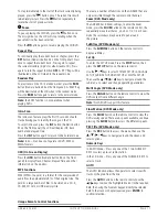
the blue wire on the  wiring loom supplies 12 Volts when the 
GD9600 is switched on and can be used to turn on an  external 
device, like the GmE GA9800 marine amplifier, or enable the 
back light on the GmE rcu9200 wired remote

.

Fill strips

screw caps

screw caps

BLACK

BLUE

Summary of Contents for GD9620B

Page 1: ...Marine Stereo System GD9620W GD9620B GD9640W GD9640B I N s t r u c t i o n m a n u a l w w w g m e n e t a u...

Page 2: ...harness Flush mount support kit and template Spare flush mount screw caps 4 Owner s manual Please immediately contact your point of purchase if any of these components are missing gme strongly recomme...

Page 3: ...ll ensure the GD9600 is destined to become the standard by which all marine stereo systems are measured Read this instruction booklet carefully drop in your favourite music selection sit back and enjo...

Page 4: ...Select 4 Loudness 5 Mute 6 Clock Time Selector 7 Mode Switch 8 LOC DX Selector 9 Stereo Mono 10 Band Selector 11 Tuning Selecting Tracks 12 Eject 13 Auto Music Search 14 EQ settings Flat Classic Rock...

Page 5: ...circular motion Do not use solvents Moisture Condensation Your GD9600 uses optical laser technology Occasionally damp or humid conditions may cause condensation to appear on the lenses inside the uni...

Page 6: ...40 into the bracket and adjust to the desired angle before tightening the gimbal knobs 5 Complete the antenna lead and electrical wiring as described later For overhead mounting the GME logos on the s...

Page 7: ...to the battery s positive terminal and the GD9600 switched ON and OFF using it s own controls 3 Connect the Black wire to the battery s negative terminal or to the common negative bus in the electrica...

Page 8: ...a maximum of 15 meters iPod Connectivity The GD9600 has a 2nd fly lead which when connected with an LEO23 optional 1 1 meter lead enables an iPod to be connected directly to the stereo Limited functi...

Page 9: ...s Briefly press the clock button again The minutes will flash Rotate the volume control left or right to set the minutes Press the Clock button again to exit the setting mode 7 Mode Pressing the MOD b...

Page 10: ...when the P EQ mode is selected CD MP3 DVD Operation Warning Do not insert discs containing anything other than CD DVD or MP3 files into the disc slot The CD DVD mechanism contains precision laser comp...

Page 11: ...approximately 8 of their original size This permits a large number of files to be stored on a CD R CD RW SD Card or USB memory stick Unique Remote Control Functions There are a number of functions on...

Page 12: ...xiliary inputs and outputs Front Panel Inputs There are standard USB and SD Card inputs located on the front panel USB The USB Input accepts USB flash memory drives loaded with MP3 files Max USB memor...

Page 13: ...te handset at the GD9600 and select the required option on the keypad Remote control functions Cautions The remote control handset is not waterproof and should be kept well away from both fresh and sa...

Page 14: ...y please call or email your local GME Sales Office within Australia and New Zealand Contact details are listed on the back page of this manual International customers should also refer to the back pag...

Page 15: ...mpedance Horizontal Resolution 500 Video System Auto PAL NTSC GENERAL DC Supply Input 11 16 Volts Negative Ground Memory Back up External Back up Memory Wire Back up Current Approximately 20 mA Overal...

Page 16: ...y The retailer will forward the unit to the closest authorised GME Service Depot in your particular area GME After Sales Service Your GME GD9600 is especially designed for the environment encountered...

Reviews: