Supplied By www.heating spares.co Tel. 0161 620 6677
14
221474C
125
electronic
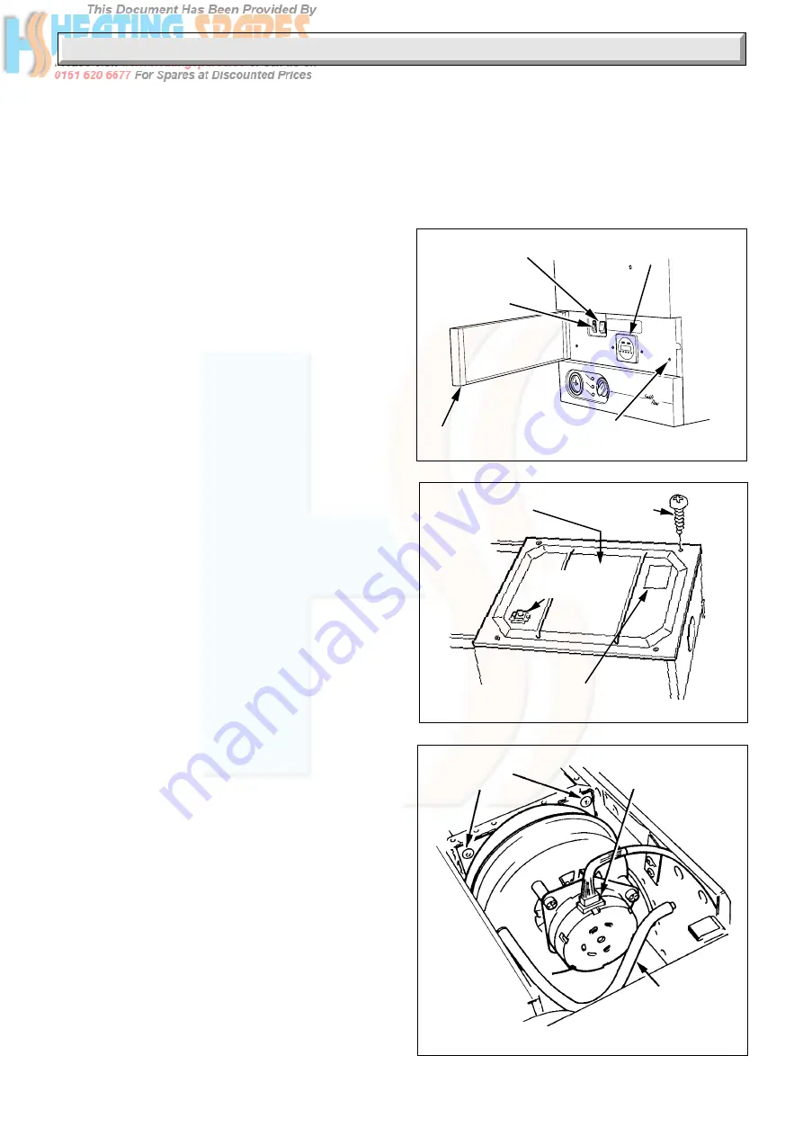
Diagram 6.3
FAN SECURING
SCREWS
Diagram 6.2
VIEWING
WINDOW
INNER CASE
COVER
SECURING
SCREW (4)
DATA
LABEL
ELECTRICAL
PLUG
AIR
PRESSURE
TUBE
4561
6920
Diagram 6.1
6504
CLOCK TIMER
RESET SWITCH AND
NEON INDICATOR
CENTRAL
HEATING
SELECTOR
SWITCH
DOOR
OUTER CASE
SECURING SCREW (2)
(IF CLOCK TIMER
FITTED(4))
6.1 Unpacking
Remove the top carton and cut out the flue template from the inner
flap.
Open the control door, see diagram 6.1.
Remove the two screws securing the outer case and then lift it at the
top and pull it forwards and off, see
diagram 6.1.
Remove the cover of the inner case, secured with four screws, see
diagram 6.2
Slacken flue collector thumb screws.
Remove the fan securing screws.
Disconnect the electrical plug connector and air pressure tube from
the fan, see diagram 6.3.
Pull the fan forwards, at the bottom and rotate to disengage the fan
outlet from rear bracket.
Take care not to damage the seal.
Tilt the fan and withdraw.
Disconnect the gas cock union and the front unions of the isolation
valves, see diagram 6.4.
Slightly loosen the clips of the gas service cock and the isolating
valves.
Remove the two boiler securing screws then remove the boiler from
the mounting frame, by pulling the studs from the clips and
unhooking it at the top.
6.2 Marking
The boiler mounting frame is the same width as the boiler case. The
flue connection is on the top.
IMPORTANT: Should internal flue installation kit (Part No. 452481)
which will enable the flue terminal to be inserted through the wall to
the outside of the building be used, provision should be made to
prevent any injury or damage due to falling debris.
Place the boiler mounting frame on the wall in the required position,
see diagram 2.1, to maintain minimum clearances. Make sure that
the isolation valves are at the bottom facing forward and that the
frame top is horizontal, then mark the four wall fixing points through
the holes in the two horizontal straps.
Position the flue template on the wall, the arrow points on the
centres of the two upper fixing points previously marked, see
diagram 6.5 which also gives dimensions.
For a rear flue, mark the position as required.
For a side flue, mark the horizontal flue centre line at the sides of the
template. Extend the flue centre line horizontally left or right to the
internal corner where the flue is required to exit to outside.
Mark the position of the circular hole, on the flue exit wall, using the
dimensions given in diagram 6.6.
From the flue position marks, check that the flue terminal will be in
a suitable position, see diagram 3.5.
6 Appliance and Flue Preparation
6.3 Flue Hole Cutting
Having marked out the flue centre, cut a hole for the flue, using,
preferably, a 130mm minimum core drill.
Note: If using the internal flue installation kit, the hole should be
150mm diameter.
Cut the hole horizontally in the wall, making sure that it does not
slope down towards the boiler.


