


0020117819_01 - 05/11 - Glow-worm
- 13 -
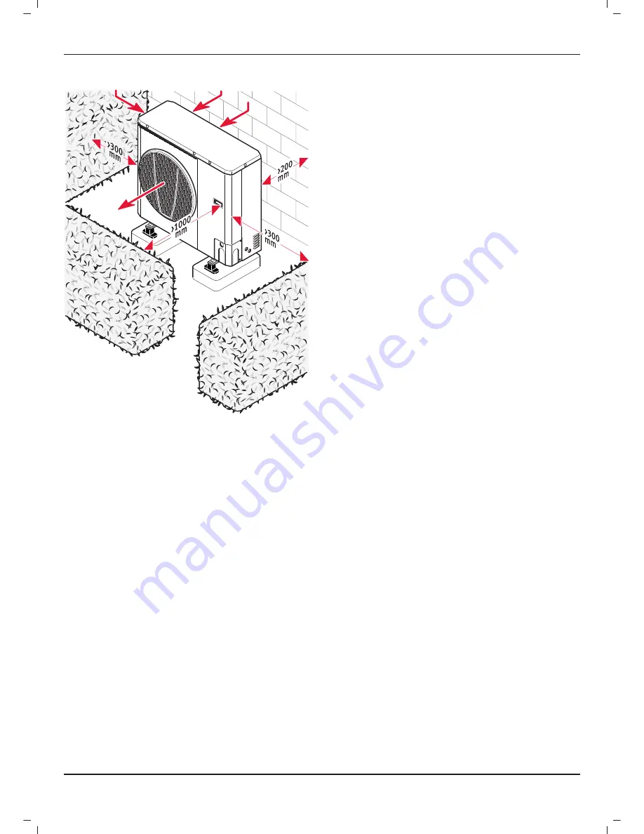
7.2 Clearances
-
Respect the minimum dimensions shown in the drawing
above in order to ensure a correct air
fl
ow and to facilitate
maintenance operations.
-
Make sure that the available space is su
ffi
cient for the
installation of the water system piping.
7.3
Command unit location
•
Install the command unit in a room protected from frost
INSTALLATION
Summary of Contents for Envirosorb2 12
Page 1: ...Envirosorb2 7 12 14 Installation and Servicing...
Page 2: ......
Page 41: ......
Page 42: ......
Page 43: ......