


23
221895A
10 Commissioning
6989
Diagram 10.1
7811
BURNER
PRESSURE
TEST POINT
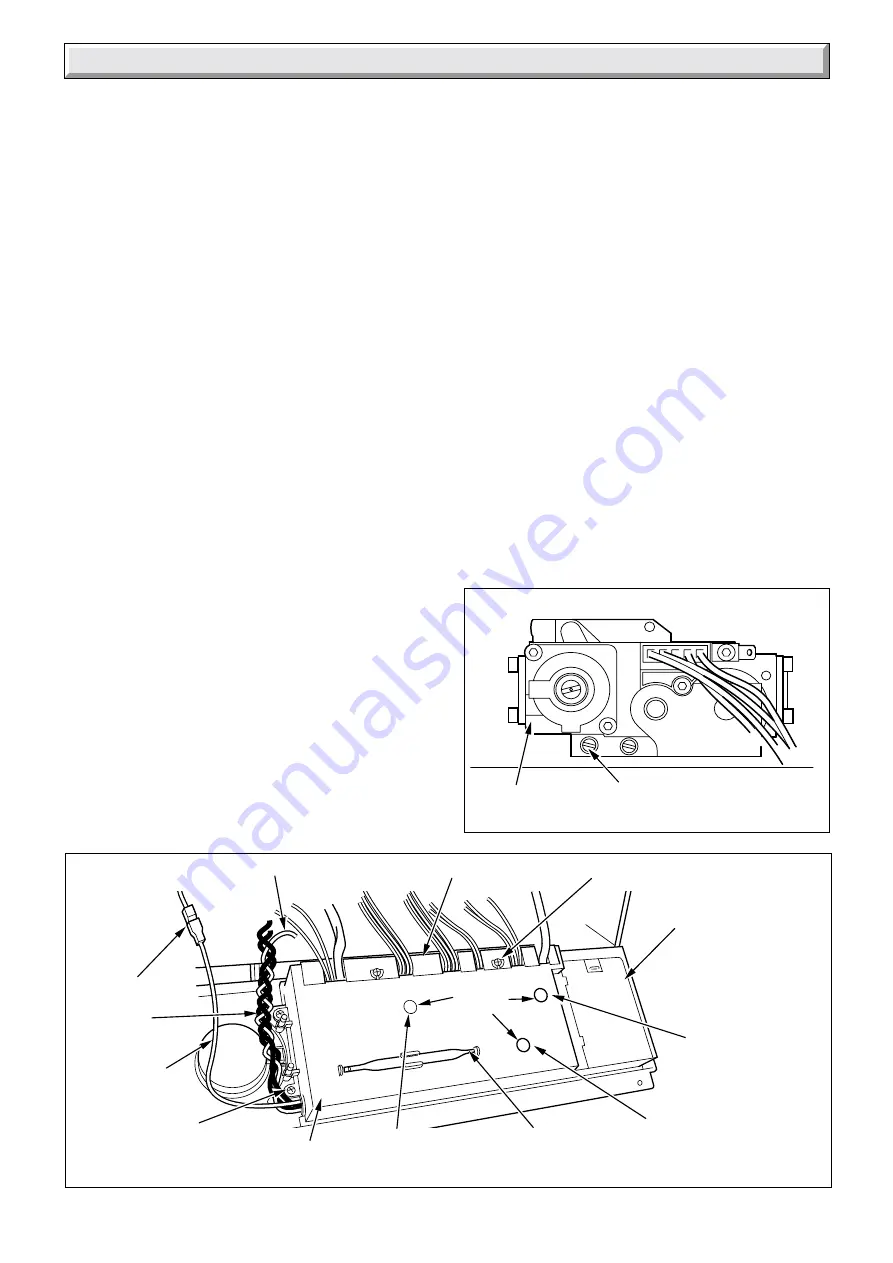
10.8 Ignition Rate
Set the mains electrical switch “B” to 0, located on the controls
fascia, see diagram 4. (Instructions for Use).
Disconnect the sensing lead at the connection, see diagram
10.2.
Set the mains electrical switch “B” to 1. The electrode will
continue to spark for (10 seconds approx.) to enable the ignition
to be set and checked before going to lockout. Check the
ignition rate is set to 6.0 mbar +/-1.0 mbar, adjust if required by
turning the ignition rate setting potentiometer using the
adjustment tool supplied, If this is not achieved before the boiler
goes to lockout the process can be repeated as required by
pressing the rest button “G”, see diagram 4. (Instructions for
Use). When set, switch the mains electrical switch “B” to 0.
Reconnect the sensing lead.
Set mains electrical switch “B” to 1, depress the rest button “G”
if required. Check the appliance operates correctly.
Isolate the boiler from the electrical supply.
Replace plastic plugs, screw cap and adjusting tool.
Disconnect the pressure gauge, tighten the burner pressure
test point screw . Test for gas soundness. Take care not to
splash any of electrical components.
Refit the control fascia.
10.9 Temperature Settings
The maximum temperature setting for the domestic hot water
outlet is 65
o
C.
The maximum flow temperature setting for central heating is
80
o
C.
10.10 Heating System - Commissioning
Check that all remote controls and integral clock are calling for
heat.
Fully open all radiator valves.
Set the heating system in operation and balance the radiators.
Refer to Section 4.6 and diagram 4.1.
Allow the system to reach maximum temperature then switch
off, isolate the boiler from the electrical supply and drain the
system rapidly whilst still hot.
Remove the inner case front.
Fill and vent the system as described in Section 10.2 “Filling the
Central Heating Circuit”. Add inhibitor, if applicable, refer to
Section 4.9 “Corrosion Inhibitor”.
GAS
CONTROL
VALVE
Diagram 10.2
CABLE ENTRY COVER
CLOCK-TIMER
COVER
CONTROL BOARD
COVER
SECURING
SCREW (4)
SECURING SCREW (2)
Slacken do not remove
BURNER PRESSURE
ADJUSTING TOOL
DOMESTIC HOT
WATER BURNER
PRESSURE
POTENTIOMETER
HEATING
BURNER PRESSURE
POTENTIOMETER
PLASTIC
PLUGS
Lower the pressure to the initial cold fill design pressure, using
the external draining tap, close to the boiler, refer Table 1 and
Section 4.10.
10.11 Completion
Fit the side panels, hook into the threaded lugs at the top. see
diagram 10.4.
Fit the case base, slide back engage the rear lugs, secure with
four screws, see diagram 10.3.
Fit the outer case front by locating it on one side then wrap it
around locating it on the opposite side, slide down locating on
to the threaded lugs at the top and behind the controls cover at
the bottom, secure with nuts ,see diagram 10.5.
Set the boiler and any remote heating control to the desired
settings, then close the control cover door.
10.12 Instruct the User
Instruct and demonstrate the lighting procedure, then advise
the user of the efficient and safe operation of the boiler.
Instruct and demonstrate the operation of any heating system
controls.
Advise the user on the use and maintenance of any scale
reducer and pass on any relevant instructional documents.
Advise the user that to ensure the continued efficient and safe
operation of the appliance it is recommended that it is checked
and serviced at regular intervals. The frequency of servicing will
depend upon the particular installation and usage, but in general
once a year should be enough.
CONNECTION
IGNITION RATE
SETTING
POTENTIOMETER
SENSING
LEAD
CHASSIS EARTH LEAD
IGNITION
LEADS (2)