


32
Installation and maintenance instructions Compact 0020313973_01
1
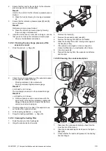
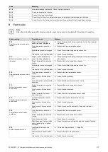
7.
Mark the gas type that is used on the gas conversion
sticker.
8.
Stick the gas conversion sticker
(1)
to the electronics
box.
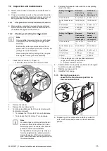
9.7
Checking the heating mode
1.
Make sure that there is a heat requirement.
2.
Activate the display of the status codes. (
◁
If the product is working correctly, the display
shows
S.04
.
▽
If the filling function for the condensate siphon has
been activated,
S.58
is displayed as a priority.
9.8
Checking the domestic hot water generation
1.
Open a hot water tap completely.
2.
Activate the display of the status codes. (
◁
If the product is working correctly, the display
shows
S.14
.
9.9
Checking leak-tightness
▶
Check the gas pipe, the heating circuit and the hot water
circuit for leak-tightness.
▶
Check that the air/flue pipe has been installed correctly.
Condition
: Room-sealed operation
▶
Check whether the vacuum chamber has been closed
tightly.
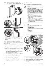
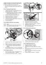
9.10
Thoroughly flushing the heating installation
("hot")
1.
Operate the appliance until the boiler and the heating
system are up to temperature.
2.
Check the heating system for leaks.
3.
Connect a hose to the drain valve located at the lowest
position of the heating system.
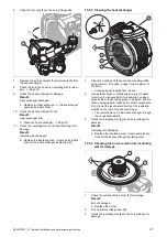
4.
Shut off the boiler, open the drain valve and all purge
valves on the radiators and allow the water to flow out
of the heating system and the boiler quickly and fully.
5.
Close the drain valve.
6.
Fill the heating system again with water as described
in "Filling and purging the heating installation"
(
7.
Re-fill the system until the system design pressure of
0,1 MPa (1,0 bar) is attained.
Note
The actual reading on the digital pressure
gauge should ideally be 0,05 MPa (0,5 bar)
plus an additional pressure corresponding
to the highest point of the system above
the base of the boiler
–
10 m head equals
an additional 1 bar reading on the pressure
gauge. The minimum pressure should not
be less than 0,1 MPa (1 bar) in any install-
ation. If the system is to be treated with an
inhibitor it should be applied at this stage in
accordance with the manufacturer’s instruc-
tions.
See the section on checking and preparing
the heating water. (
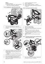
8.
Install the front casing. (
10 Adapting the unit to the installation
10.1
Adapting the heating settings
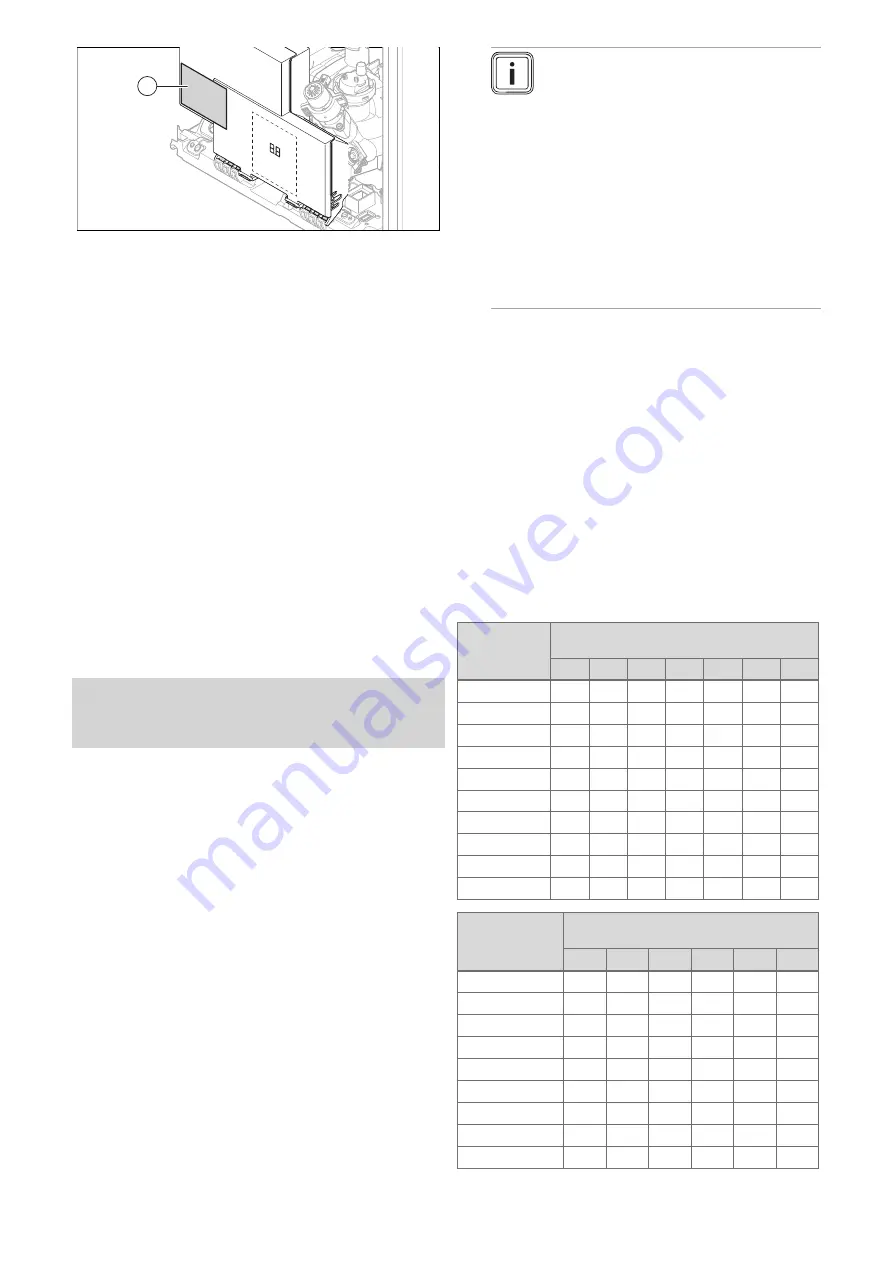
10.1.1 Burner anti-cycling time
To prevent frequent switching on and off of the burner and
thus prevent energy losses, an electronic restart lockout
is activated for a specific period each time the burner is
switched off. The burner anti-cycling time is only active for
the heating mode. Switching on domestic hot water mode
during the burner anti-cycling time has no effect.
You can use diagnostics code
d.02
to set the maximum
burner anti-cycling time (factory setting: 20 min.).
T
Flow
(target)
℃
Set maximum burner anti-cycling time
min
1
5
10
15
20
25
30
30
2.0
4.0
8.5
12.5
16.5
20.5
25.0
35
2.0
4.0
7.5
11.0
15.0
18.5
22.0
40
2.0
3.5
6.5
10.0
13.0
16.5
19.5
45
2.0
3.0
6.0
8.5
11.5
14.0
17.0
50
2.0
3.0
5.0
7.5
9.5
12.0
14.0
55
2.0
2.5
4.5
6.0
8.0
10.0
11.5
60
2.0
2.0
3.5
5.0
6.0
7.5
9.0
65
2.0
1.5
2.5
3.5
4.5
5.5
6.5
70
2.0
1.5
2.0
2.5
2.5
3.0
3.5
75
2.0
1.0
1.0
1.0
1.0
1.0
1.0
T
Flow
(target)
℃
Set maximum burner anti-cycling time
min
35
40
45
50
55
60
30
29.0
33.0
37.0
41.0
45.0
49.5
35
25.5
29.5
33.0
36.5
40.5
44.0
40
22.5
26.0
29.0
32.0
35.5
38.5
45
19.5
22.5
25.0
27.5
30.5
33.0
50
16.5
18.5
21.0
23.5
25.5
28.0
55
13.5
15.0
17.0
19.0
20.5
22.5
60
10.5
11.5
13.0
14.5
15.5
17.0
65
7.0
8.0
9.0
10.0
11.0
11.5
70
4.0
4.5
5.0
5.5
6.0
6.5
Summary of Contents for Compact 24c-AS/1
Page 59: ......


