110-013-079 REV E
ECO 202802 Date Effective: JUNE 2017
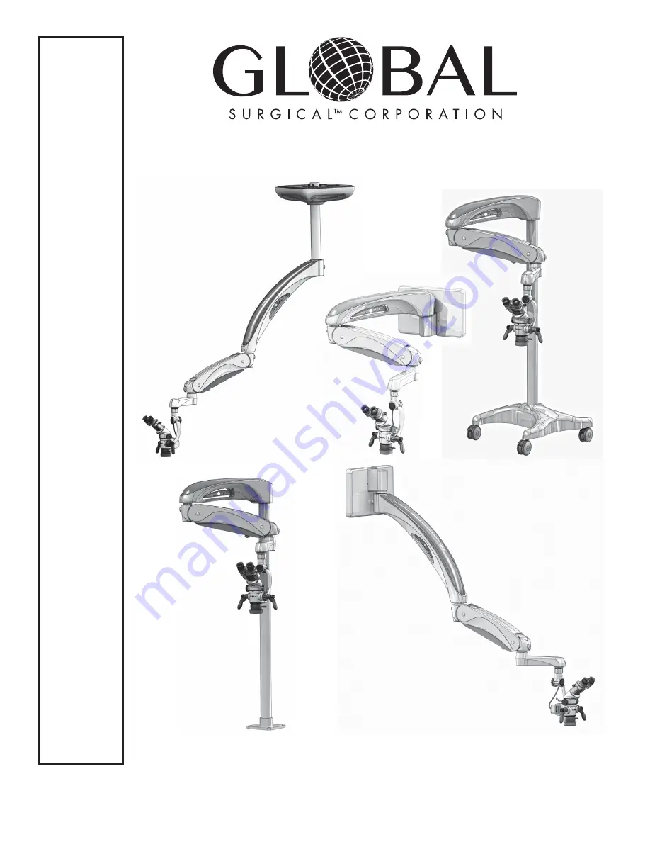
A-Series
TM
Surgical Operating
Microscope System
OWNER’S MANUAL
M A730 Series
Controlled Document
Not T
o Be Reproduced
Page 1: ...110 013 079 REV E ECO 202802 Date Effective JUNE 2017 A Series TM Surgical Operating Microscope System OWNER S MANUAL M A730 Series Controlled Document Not To Be Reproduced ...
Page 2: ...____________________________ Customer Order Number __________________________________________ 3610 TREE COURT INDUSTRIAL BLVD ST LOUIS MO 63122 1 800 861 3585 IF OUTSIDE THE USA 1 636 861 3388 COPYRIGHT 2015 GLOBAL SURGICAL CORPORATION NO PART OF THIS PUBLICATION MAY BE COPIED PHOTOCOPIED REPRODUCED TRANSLATED OR REDUCED TO ANY ELECTRONIC MEDIUM OR MACHINE READABLE FORM IN WHOLE OR IN PART WITHOUT...
Page 3: ...Congratulations on your purchase of the A Series Surgical Operating Microscope System We truly appreciate your business and we re grateful for the trust you ve placed in us ...
Page 4: ...ve Lens 4 8 Section 5 Operating Instructions 5 1 5 1 Turning On The System 5 1 5 2 Description and Location of Controls 5 1 5 3 Counterbalancing Adjustment 5 2 5 4 Spring Arm Tension Adjustment 5 2 5 5 Pivot Adjustment 5 3 5 6 Roll Angle Adjustment 5 3 5 7 Pitch Angle Adjustment 5 3 5 8 Floorstand Locking Casters 5 3 5 9 Microscope Maneuvering Handles 5 3 5 10 Microscope Components 5 4 5 11 Magnif...
Page 5: ...ervice and Warranty 8 1 8 1 Warranty Information 8 1 8 2 Technical Services Department 8 2 Section 9 Technical Information 9 1 9 1 Microscope Support System Specifications 9 1 9 2 Binocular Focal Lengths 9 1 9 3 M A801 LED Storage and Operations Specifications 9 2 9 4 A Series Microscope Total Magnification Chart 9 3 9 4 Finding Total Magnification 9 4 9 5 Effects of Changing Components 9 4 ...
Page 6: ...is symbol indicates an explosion hazard WARNING This symbol indicates a situation in which incorrect handling through disregard of a warning might result in death or serious personal injury CAUTION This symbol indicates a situation in which incorrect handling through disregard of a caution might result in personal injury or may result in damage to property NOTICE This symbol indicates a message to...
Page 7: ...MMABLE ANESTHETICS WARNING CONNECTING EQUIPMENT TO THE MULTIPLE SOCKET OUTLET EFFECTIVELY LEADS TO CREATING A MEDICAL ELECTRICAL SYSTEM AND THE RESULT CAN BE A REDUCED LEVEL OF SAFETY WARNING IT IS HIGHLY RECOMMENDED THAT THE INSTALLATION OF THIS EQUIPMENT BE PERFORMED BY QUALIFIED TECHNICIANS INSTALLATION BY UNQUALIFIED INDIVIDUALS COULD RESULT IN PERSONAL INJURY WARNING MINIMIZE SKIN EXPOSURE BY...
Page 8: ...AUTION Replacement parts such as cables must be purchased through Global Surgical to ensure proper compliance requirements The use of other cables may affect EMC performance Unauthorized use of these items will void warranty and may cause injury to you others and or the equipment CAUTION When used in clinical or residential areas near radio or TV units this equipment may be subjected to radio inte...
Page 9: ...RANSPORT POSITION CAUTION This equipment needs special precautions regarding EMC and needs to be installed and put into service according to the EMC information provided in the installation manual 110 013 080 M A730 Series Installation Manual NOTICE Portable and mobile RF communications equipment can affect medical electrical equipment See the owner s manual for each electrical component for speci...
Page 10: ...sure no components are still within NOTICE Save this manual for future reference NOTICE If you have ordered accessories then some of these may be assembled to the unit while others are supplied unassembled Please examine the content of the box thoroughly If any accessories require assembly then instructions will be included All shipping materials should be retained until it has been determined tha...
Page 11: ...vide maneuverability and sturdy stable support for the microscope and coupler arm assemblies These systems fold into convenient storage positions when not in use 3 2 Microscope Support Systems Configurations The A Series Microscope Support System is available in four configurations Floor Stand Support System Model M A730F The floor stand support system model is designed for portability around the ...
Page 12: ...cation within the office examination room M A730FM FLOOR MOUNT M A730FMT FLOOR MOUNT THROUGH THE FLOOR shown with M A730 HA Arm System M A1006 Microscope M A1022 10 Binocular M A1061 D50 Beamsplitter M A1017 45 Binocular Extender M A1028 250 Objective Lens M A730C CEILING MOUNT M A730 C8 Ceiling Mount for a mounting height of 8 foot M A730 C9 Ceiling Mount for a mounting height of 9 foot M A730 C1...
Page 13: ... and folds flat against the wall for convenient storage M A730W HIGH WALL MOUNT shown with M A730 45A Arm System M A1006 Microscope M A1022 10 Binocular M A1061 D50 Beamsplitter M A1017 45 Binocular Extender M A1028 250 Objective Lens M A730W WALL MOUNT shown with M A730 HA Arm System M A1006 Microscope M A1022 10 Binocular M A1061 D50 Beamsplitter M A1017 45 Binocular Extender M A1028 250 Objecti...
Page 14: ...tion the M A1004 provides 4 steps of magnification and the M A1006 Microscope provides 6 magnification steps Each of the A Series Microscopes may be used with a variety of A Series binoculars objective lenses and other accessories M A801 LED The A Series M A801 LED Light Source provides light to the surgical site for illumination and improved optical clarity ...
Page 15: ...t Beamsplitter The dual port beamsplitter models have two 2 mounting ports for camera adapters This allows the simultaneous use of a still camera and video camera if so desired but other configurations are certainly feasible The dual port beamsplitters can be configured with either one 50 50 prism and one 95 5 prism M A1061 DVA50 or with two 50 50 prisms M A1061 D50 The beamsplitter can mount to t...
Page 16: ...other 95 of the light passes through to the user s eye The beamsplitter can mount to the microscope with the port oriented toward the user s right or left depending on personal preference The choice of which prism to use should be based on the type of camera intended to be mounted to the microscope M A1017 Carr Adapter 45 Binocular Extender Provides ergonomic benefits by positioning the binocular ...
Page 17: ...cope without having to move the microscope This promotes optimal ergonomic comfort and minimal adjustment throughout multiple procedures M A517HD1080 Series HD Color Video Camera The M A517HD1080 Series high definition camera outputs HDMI video at true 1080p HD resolution The 1 3 C mount design offers a compact and lightweight HD video solution The on camera push button is used for one push white ...
Page 18: ...se in a wide variety of office applications This arm can be used to avoid other obstacles in offices such as x ray units or cabinets Eyecups M 1039GL Long Silicone Eyecup for A and G Series Binocular 5 8 inches tall for Aand G Series binocular this is the ideal eyecup for users who do not wear glasses M 1039G Low Profile Short Silicone Eyecup for A Series Binocular Low profile 5 16 inches silicone...
Page 19: ...e to a medical equipment system The maximum permitted load for the microscope system is 240 VAC Multiple Socket Outlet WARNING ONLY CONNECT ITEMS THAT GLOBAL SURGICAL HAS SPECIFIED AS BEING COMPATIBLE WITH THE MICROSCOPE SYSTEM CONNECTING EQUIPMENT THAT IS NOT INTENDED FOR USE WITH THE MICROSCOPE SYSTEM TO THE MULTIPLE SOCKET OUTLETS MAY RESULT IN INJURY AND OR DAMAGE TO THE MICROSCOPE SYSTEM WARN...
Page 20: ...aped slot at the rear of the binocular base is installed over the slotted screw in the binocular retaining ring 4 Tighten the set screw When the microscope body and the binocular head are properly aligned the binocular head will not rotate in the binocular retaining ring NOTICE M A1047LFM Laser Filter M A1019 Binocular Rotation Ring M A512 Dual Iris Diaphragm M A1061 D50 M A1061 DVA50 Dual Port Be...
Page 21: ...cluded with each accessory 1 Ensure the lock ring is threaded down fully on the Multi Focal lens before installing the lens on the microscope body 2 Thread the Multi Focal lens into the microscope body in the direction of the arrow shown until the lens stops 3 The knob location can be positioned for user comfort Back the lens out of the microscope body NO MORE THAN 1 FULL TURN to position the knob...
Page 22: ... used See Section 5 13 M A801 LED Light Source Operation or the LED owner s manual 110 013 081 for instructions If set up with a wall switch make sure the wall switch is turned on and then depress the LED power button To safely terminate the operation of the microscope system unplug the microscope or turn off the microscope via wall switch where applicable 5 2 Description and Location of Controls ...
Page 23: ...ing the counterbalance ensure that all accessories are installed on the microscope and the spring arm tension adjustment knob is loose To loosen the spring arm tension adjustment knob turn the knob clockwise Insert the 3 16 hex wrench into the center hex socket screw located under the end of the spring arm assembly that attaches to the horizontal arm and turn the tool to the right clockwise if the...
Page 24: ...nd Locking Casters To secure the support system after it is rolled to its desired location engage the locks on the casters The lock is pushed down to obstruct regular wheel movement This fixes the support system into a desired place You can pull up the caster lock to release the wheel and move the support system if necessary See Figure 5 2 5 9 Microscope Maneuvering Handles Maneuvering handles can...
Page 25: ... is facing the indicator arrow on the left side of the microscope body See Section 9 Technical Information for the magnification and focal length information 5 10 Microscope Components Figure 5 5 Microscope Components Coupler Arm Magnification Selector Knob Microscope Maneuvering Handle Microscope Head Microscope Maneuvering Handle Magnification Selector Knob Pitch Angle Adjustment Knob Objective ...
Page 26: ... microscope above a flat stationary surface with the bottom of the objective lens parallel to the surface 3 Using a pen or pencil mark an X on a piece of white paper for a focusing target and place it in the center of the illumination field of the microscope 4 Depress the diopter tension lever and set the diopter adjustment rings on both eyepieces to 0 See Section 5 18 for additional information 5...
Page 27: ...ated See Figure 5 6 WARNING BEFORE operating the light source refer to the Owner s Manual 110 013 081 for any warnings and cautions associated with the use of the Light Source to ensure safe operation NOTICE The LED light source has been tested according to IEC 60601 2 57 Non laser light source The test results show no photobiological hazard associated with the use of this LED light source as it i...
Page 28: ...mes Pressing and holding the button will only increase the brightness to the next higher setting The light source has a recall feature This feature remembers the last level of brightness used before being powered off Any time the light source is powered on the brightness level will be at the last level used 5 15 Filter The LED light source emits white light which includes all the colors of light c...
Page 29: ...e adjustable to provide maximum comfort for the user To lower the eyecup grasp the rubber eyecup and turn it clockwise Turning it counterclockwise will raise the eyecup The eyecups are properly adjusted when the user s eyes or glasses are touching the eyecups with the image through the microscope in full view Reference lines are provided on the outside surface of the eyecups to verify that both ar...
Page 30: ...udden and unexpected power surge To replace the fuses follow the steps below 1 Unplug the power cord from the outlet to remove power to the system 2 Remove the screw s holding the cover on the arm See Figure 5 10 3 Remove the cover 4 Open the fuse compartment cover 5 Remove both fuses even if only one fuse is blown 6 Replace with two 2 new 5mm x 20mm cylinder slow blow 6 Amp 250 Volt Fuses 7 Repla...
Page 31: ...mp 250V Fuses Horizontal Fixed Arm Version Remove Screw Open Fuse Compartment Replace with Two 2 6 Amp 250V Fuses Remove Cover Remove 2 Screws and Remove Cover 45 Arm Version NOTICE If your new fuse blows soon after installing it you could have problems in that circuit Contact Global Surgical Technical Support for assistance ...
Page 32: ...aying optical components 4 Do not allow cleaning agents or liquids to enter the power input 5 Use any disinfectant agents which are commonly applied while disinfecting surfaces of electric medical equipment Such disinfectant agents are usually in the form of sprays or damp cloths 6 Follow the instructions given by the manufacturer of the disinfectant solution 6 2 Cleaning the Microscope Optics The...
Page 33: ...nt is installed level and plumb If floorstand arms are still drifting move to a different location on the floor and ensure column screws are tight Floorstand seems unstable Ensure that both weights are installed in the base under the plastic cover Floorstand is difficult to roll Ensure that all the casters are unlocked LED light source does not turn on Remove horizontal arm spring arm or 45 degree...
Page 34: ...low you to track the package in the event it does not arrive Global also recommends you insure the package This warranty shall not be applicable to l any electrically driven products sold by the Company II any products which are not manu factured by the Company which may be attached to the product such as video equipment camera equipment recording devices moni tors printers III any components whic...
Page 35: ...e has information about additional products and services and can be reached by using the online at http www globalsurgical com Service Information In the event of any malfunction you should immediately contact the Global Surgical Technical Services Department for as sistance A Customer Identification Number and Customer Order Number will be needed when contacting the Techni cal Services Department...
Page 36: ...x 8 51 mm x 203 mm or larger joists on 16 406 mm centers Use Model M A730 C8 9 2 74 m Mounting Surface Use Model M A730 C9 Same as Model M A730 C8 except column is 12 305 mm longer 10 3 05 m Mounting Surface Use Model M A730 C10 Same as Model M A730C8 except column is 24 610 mm longer Custom Special construction by independent contractor must meet the above specifications If mounting to a ceiling ...
Page 37: ...lative Humidity Air Pressure 10 to 40 C 50 to 104 F 0 to 95 700 to 1060 kPa Storage Environment Temperature Relative Humidity Air Pressure 20 to 60 C 4 to 140 F 0 to 95 700 to 1060 kPa Dimensions 4 70 in 119 mm W x 3 25 in 83 mm H x 3 0 in 76 mm D Weight 1 65 lbs 74 kg 140g IEC 62471 Risk Group 0 Regulations Standards Conforms to AAMI Std ES60601 1 IEC 60601 1 6 Certified to CSA Stds C22 2 s 60601...
Page 38: ...2 6 4 0 6 4 8 0 10 0 16 0 24 0 160 225 10 2 3 3 6 5 7 7 1 8 9 14 2 21 3 160 250 10 2 1 3 2 5 1 6 4 8 0 12 8 19 2 160 300 10 1 8 2 7 4 3 5 3 6 7 10 7 16 0 160 350 10 1 5 2 3 3 7 4 6 5 7 9 1 13 7 125 200 12 5 2 6 3 9 6 3 7 8 9 8 15 6 23 4 125 225 12 5 2 3 3 5 5 6 6 9 8 7 13 9 20 8 125 250 12 5 2 1 3 1 5 0 6 3 7 8 12 5 18 8 125 300 12 5 1 7 2 6 4 2 5 2 6 5 10 4 15 6 125 350 12 5 1 5 2 2 3 6 4 5 5 6 8...
Page 39: ... From higher to lower i e 2X to 1X Decreases Increases No Change No Change From lower to higher i e 1X to 2X Increases Decreases No Change No Change Eyepiece Power From higher to lower i e 12 5X to 10X Decreases Increases No Change No Change From lower to higher i e 10X to 12 5X Increases Decreases No Change No Change Table 9 5 Effects of Changing Microscope Components 9 4 Finding Total Magnificat...
Page 40: ...Global Surgical Corporation 3610 Tree Court Industrial Blvd St Louis MO 63122 EMERGO EUROPE Prinsessegracht 20 2514 AP The Hague The Netherlands 91613 ...