background image


Global Water 

800-876-1172 

 globalw.com 


- 24 - 


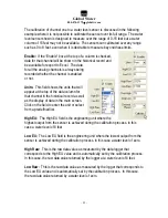
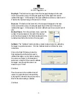
Disp High: 

 This field sets the upper limit of the bar graph displayed in the main 

screen and provides a way of scaling the graph beyond the upper limit used to 
calibrate the logger.  In this example, the upper calibration point was a water level of 

8 feet but the maximum range of the sensor is 16 feet. 

 
Disp Low:  

This field sets the lower limit of the bar graph displayed in the main 

screen and provides a way of scaling the graph beyond the lower limit used to 

calibrate the logger.  In this example, the lower calibration point was a water level of 
zero. 

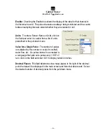
Decimal Places:

  From the pull-down menu, select the 

number of decimal places to the right of the decimal  

point that should appear in the historical data and in the 
numerical data field at the bottom of the bar graph. 


Calibrate:

  The “Calibrate” button provides a simple 4-step process for calibrating 

the logger to a particular sensor.  Click the Calibrate button and follow the menu 
instructions. 

 
Click on the High EU field and enter the  
high engineering unit that will be used to 
calibrate the logger, 

not the highest reading


the sensor can output

. In this example of 

water level, a depth of 8 feet used to calibrate 
the logger, even though the sensor can 
measure up to 15 feet. 

 
Click Next. 
 
Place the sensor in the condition that will 

cause it to output the level corresponding  
to the high EU entered in the previous menu. 
Wait for the data reading to stabilize. 
 

Click Next. 

Summary of Contents for FR0000K

Page 1: ...w com 1 GL500 2 1 Data Logger Covers GL500U 2 1 and GL500S 2 1 Data Loggers Global Water Instrumentation Inc 11390 Amalgam Way Gold River CA 95670 T 800 876 1172 Int l 916 638 3429 F 916 638 3270 glob...

Page 2: ...will be happy to help Table of Contents I Checklist 3 II Inspection 3 III Warranty 3 IV Specification 4 V System Requirements 5 VI Software Installation 5 VII Direct Connection 8 VIII Modem Connection...

Page 3: ...ts that its products are free from defects in material and workmanship under normal use and service for a period of one year from date of shipment from factory Global Water s obligations under this wa...

Page 4: ...0 60 Seconds Digital Input Switch closure input Maximum Input Voltage 24VDC Maximum Frequency 100Hz Minimum Pulse Width 2mS Maximum Count 65 535 16 Bit Sample Modes Fixed Interval Programmable from 1...

Page 5: ...action is needed You can start using the logger by opening the Global Logger application program Skip the next section USB Driver Installation GL500U Only With the installation CD in the CDROM drive a...

Page 6: ...software Click No not at this time when asked if Windows Update can search for software Click Next 2 Do not let Windows automatically install the software Click Install from a specific location Click...

Page 7: ...no harm will come to your computer 5 The first half of the installation is complete The Hardware Wizard must make two passes Click Finish 6 Two drivers are required so the Hardware Wizard repeats the...

Page 8: ...ed However this communication software also supports loggers which may be programmed in a Fixed Baud Rate Mode This is useful in telemetry applications particularly when using Global Water data logger...

Page 9: ...so be used Next select the desired baud rate from the Baud Rate menu Generally the fastest rate of 115 200 is used although long cables or other factors may require a slower setting Click Connect to m...

Page 10: ...he additional handshaking performed during modem communication The Global Logger software will operate significantly slower than during a direct connection The Global Logger software will remember the...

Page 11: ...ting the normal Global Logger screen will appear and operate exactly as if a direct connection was made All options and features work the same but at a reduced communication speed When connecting the...

Page 12: ...access the logger for extended periods of time you disconnect to increase battery life Interface cables may remain connected To disconnect click on the Disconnect button This label on this button wil...

Page 13: ...rent connection status Logger Name The logger name is a user defined name associated with a particular logger to identify one from another It is programmed in the Setup menu as described later and is...

Page 14: ...ogger software to take and display a single reading as well as update the rest of the fields on the screen This data reading is not stored in the historical record and does not affect the normal recor...

Page 15: ...and as pulses are applied to the pulse inputs the Pulse Channel fields will update the count At the end of the normal one minute sampling interval the total number of pulses will be stored in memory a...

Page 16: ...cussion of that subject and links to related topics underlined in blue Clicking on the link will bring up a new window with specific information on that topic In this case Sensor Warm up time in the G...

Page 17: ...originally indicated At the top of the screen is shown the name assigned to the logger and the number of recordings that have been retrieved At the bottom of the screen are three buttons Pack Save to...

Page 18: ...og Digital and General The first screen to appear is General Setup At the top of the setup screen is a toolbar with three options File Action and Help File The File option allows you to exit the setup...

Page 19: ...will restore all of the analog digital and general setup information fields to default values Only the setup menus are changed the data logger must still be programmed with the new default values A wa...

Page 20: ...Rate Leave this set to Auto Baud Rate Only change this to a fixed baud rate if planning to use this logger in a telemetry application such as using Global Water s Global Access radio modem software O...

Page 21: ...hannel 1 only and the deviation is measured in Raw Data units where the approximate raw data range is from 0 65535 corresponding to 0 20mA To find the actual number of raw data units per engineering u...

Page 22: ...amming the alarm times If left enabled changing and reprogramming any of the setup parameters will restart the alarm timers and could cause the logger to stop recording XIV Analog Setup The Analog Set...

Page 23: ...f the data column for that channel in the historical record as well as the display of data in the main screen Click on the field to enter the unit or select from a predefined list High EU The High EU...

Page 24: ...menu select the number of decimal places to the right of the decimal point that should appear in the historical data and in the numerical data field at the bottom of the bar graph Calibrate The Calibr...

Page 25: ...n this example the value is zero feet which is the lowest calibration point and water level Click Next Place the sensor in the condition that will cause it to output the level corresponding to the low...

Page 26: ...from a list of units predefined in the pull down menu Value for a Single Pulse The number of pulses is multiplied by this number to scale it to rainfall water flow etc If a pulse channel is connected...

Page 27: ...k to the main screen If no settings have changed Exit will occur immediately If settings have changed but not saved yet a message will appear that asks the user if they would like to save them now If...

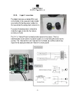
Page 28: ...the analog input connector is To access the analog sensor connections inside the logger loosen the four screws and remove the lid The V or Sensor Power terminal provides power to the sensor This is a...

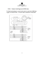
Page 29: ...76 1172 globalw com 29 XVIII Modem Cable Diagram GL500S Only The following wiring diagram is used to make a cable to connect the GL500S Data Logger to an external modem A Pre wired cable is available...

Page 30: ...atteries need replacing b Check the logger and sensor calibration numbers in the Setup Menu Recalibrate the logger if necessary As a precaution save the setup file first as described in section XI Iss...

Page 31: ...pecific problems relating to the product Be prepared to describe the problem you are experiencing including specific details of the application installation and any additional pertinent information In...

Page 32: ...risks of electrical equipment operating within certain voltage ranges According to the following standards EN61010 1 2001 Electro Magnetic Directives 2004 108 EC Requirements to prevent electrical and...

Reviews: