background image

Setting up

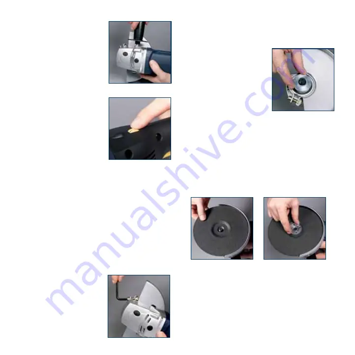
Multi position front handle

Screw the multi position front
handle (9) into the most
suitable mounting point (6)
(left side, right side or at the
top) to suit the task on hand.

Variable Speed

The POL1450 is fitted with a
variable speed dial (3) that
allows you to adjust the speed
to suit the application and
material. The tool operates
between the speeds of 
1500 RPM – 6500 RPM, the
higher the number on the
variable speed dial, the higher
the speed. For polishing and buffing applications it is
recommended that a lower speed (1500 RPM) is used. For
sanding applications it is recommended that a medium
speed (3500 RPM) is used to provide efficient material
removal, for grinding applications the maximum speed
(6500 RPM) should be selected.

Warning.

Do not operate the machine with a polishing

bonnet attached above 1500 RPM (Position 1 on the
variable speed dial).

Operation in grinder mode

Fitting the grinding disc

Switch off the tool and disconnect it from the power
supply.

Warning.

The guard must

always be attached and secured
to the tool during angle
grinding applications.
1. Fit the guard (15) onto the

spindle collar and rotate to
the required working

position. The closed side of the guard must always be
facing the operator.

2. Insert the guard securing

screw and tighten using the
matching nut. Use the
supplied Allen key to securely
tighten the screw.

3. Place the inner flange (16)

onto the spindle making sure
it fits securely.

4. Ensure that the non-threaded

inner flange is on the spindle
and located correctly. The two machined flat sections
on the inner flange must face the angle grinder and
locate in the matching positions on the spindle.

5. Place the grinding or cutting disc on top of the inner

flange ensuring the bore fits into the raised centre
section of the flange.

6. Place the outer flange (17) over the spindle. For

grinding and cutting discs which are 5mm or thicker, fit

the outer locking flange (17) with the raised centre
section inwards towards the wheel. This helps to locate
the disc on the flanges.

7. For grinding and cutting discs which are less than 5mm

in thickness, fit the outer locking flange with the raised
centre section facing outwards, away from the disc.

8. Failure to fit the outer flange correctly as detailed

above will result in the outer flange tightening on the
inner flange but not clamping the disc.

9

Summary of Contents for POL1450

Page 1: ...POL1450 030901 Ed8 DR ...

Page 2: ... safety rules for sanders 5 Additional safety rules for angle grinders 6 Additional safety rules for polishers 7 Accessories 7 Unpacking 7 Know your product 8 Setting up 9 Operation in grinder mode 9 Operation in sander mode 11 Operation in polisher mode 12 Replacing the rubber disc 13 Maintenance 13 Cleaning 13 General inspection 13 2 ...

Page 3: ...721 in New Zealand Introduction Your new GMC power tool will more than satisfy your expectations It has been manufactured under stringent GMC Quality Standards to meet superior performance criteria You will find your new tool easy and safe to operate and with proper care it will give you many years of dependable service Caution Carefully read through this entire Instruction Manual before using you...

Page 4: ...work piece and parts of work piece Disc fracture Catapulting of disc pieces Damage to hearing if effective earmuffs are not worn Do not use discs that are deformed or cracked Always remove the plug from the mains socket before making any adjustments or maintenance including changing the disc Warning When using power tools basic safety precautions should always be taken to reduce the risk of fire e...

Page 5: ...tch what you are doing Use common sense Do not operate a power tool when you are tired 19 Check for damaged parts Before using a tool check that there are no damaged parts If a part is slightly damaged carefully determine if it will operate properly and perform its intended function Check for alignment of moving parts binding of moving parts breakage of parts proper mounting and any other conditio...

Page 6: ...scs for grinding or metal wheels on masonry Watch out for flying sparks Hold the tool at an angle of approximately 15º to 30º to the work piece surface Let the disc do the grinding or cutting at a reasonable feed as overloading will occur if too much pressure is applied and the disc slows resulting in inefficient cutting and possible damage to the motor When using the grinder use safety equipment ...

Page 7: ...errupted when operating the tool complete the process and switch off before looking up Periodically check that all nuts bolts and other fixings are properly tightened Always use the front handle and ensure a good grip on the polisher rear handle with one hand and the front handle with the other hand before proceeding with any work Make sure that the disc is not in contact with the work when you st...

Page 8: ...n 3 Variable speed dial 4 Rear handle 5 Soft grip 6 Mounting points for the multi position front handle 7 On Off switch 8 Lock off button 9 Multi position front handle 10 Rubber disc 11 Polishing sponge 12 Polishing bonnet 13 Sanding disc 14 Grinding disc 15 Disc guard 16 Inner flange 17 Outer flange 8 12 9 Sander Polisher Disc assembly 2 1 3 7 8 4 5 6 10 13 11 12 Grinder Depressed disc thicker th...

Page 9: ...ations 1 Fit the guard 15 onto the spindle collar and rotate to the required working position The closed side of the guard must always be facing the operator 2 Insert the guard securing screw and tighten using the matching nut Use the supplied Allen key to securely tighten the screw 3 Place the inner flange 16 onto the spindle making sure it fits securely 4 Ensure that the non threaded inner flang...

Page 10: ... disc from digging into the work piece first draw the grinder across the work piece towards the operator Once the leading edge of the disc is slightly worn down grinding can be conducted in either direction 5 Once the grinding or cutting is finished remove the disc from the work piece To turn the tool off release the on off trigger switch The lock off button 8 will re engage 6 The tool will stop P...

Page 11: ...ool are in good condition Plug the cordset into the mains socket 2 To start the tool depress the lock off button 8 and squeeze the on off trigger switch 7 Note Once the tool has started there is no need to maintain pressure on the lock off button 3 Do not overload the tool so that the disc slows down Let the tool do the work rather than applying pressure The weight of the tool alone provides suffi...

Page 12: ... polishing sponge and secure it with a simple overhand knot 6 Tuck the drawstring into the bonnet 7 Remove the bonnet by loosening the drawstring and slipping the bonnet off the polishing sponge Applying polish Most polishes are either in paste or liquid form Before using any polish read all directions on appropriate applications and proper use Switching on and off 1 To start the tool first ensure...

Page 13: ...ring that it is tight on the spindle and that it rotates fully and does not wobble unduly 5 Run the grinder sander polisher at no load for at least one minute to ensure the new disc is in good condition Make sure you are wearing all the safety gear and that you face the polisher away from you Maintenance All the bearings are sealed ball bearings lubricated for life and require no maintenance Power...

Page 14: ...14 ...

Page 15: ...15 ...

Page 16: ...ce to make suggestions or give comments about any GMC product With continuing product development changes may have occurred which render the product received slightly different to that shown in this instruction manual The manufacturer reserves the right to change specifications without notice Note Specifications may differ from country to country The GMC 777 Helpline operates from 7am to 7pm 7 day...

Reviews: