background image

15

Need help or have any questions?  Call us at 1-714-963-0329 or send us an Email at [email protected]

The X-Terminator Pro features front and rear gear differentials that each feature five o-ring seals and cup-style housings.  Both differentials
are packed with differential grease that is good for most driving conditions.

You can make fine-tuned adjustments to each differential by removing the differentials from the chassis, opening them up and replacing
the grease already inside the differentials with heavy-weight silicone shock oil.  Removal, disassembly and reinstallation of the differentials
can be done, using the exploded parts diagram included with your kit.

Adding heavier silicone oil will tighten the differentials and adding lighter silicone oil will loosen the differentials.  If your buggy feels

loose during turns, you can tighten the front differential or loosen the rear differential.  If your buggy is pushing during turns, you can
loosen the front differential or tighten the rear differential.  We recommend using silicone shock oil weights between 30,000 and 100,000.

WARNING

  We don't recommend attempting to make adjustments to the differentials unless you have knowledge of how to

remove, disassemble and reassemble gear differentials.  If you don't reassemble the differentials properly, damage to the differentials
will happen quickly and will not be covered by warranty.

Step 6:  Adjusting the Front and Rear Differentials

Out of the box, the X-Terminator Pro has a stiff sway bar installed.  This sway bar will give good performance in most conditions.  We
have included a more flexible sway bar should you want to change it.

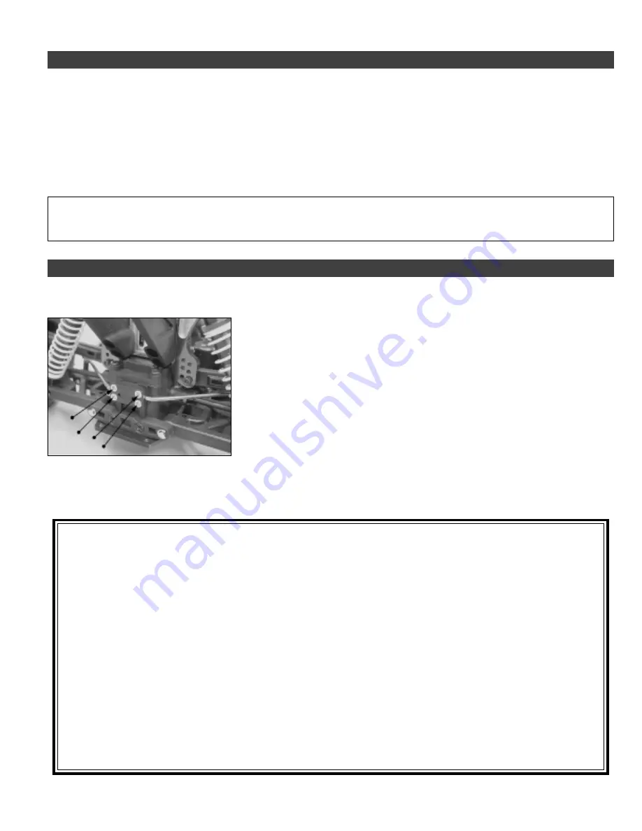
Step 7:  Changing the Rear Sway Bar

To remove the stock sway bar, first loosen the grub screws in the collars at each end of the
sway bar.  Next, remove the four screws that hold the sway bar block in place, then
remove the sway bar block and pull the sway bar out.  Replace the sway bar with the more
flexible one.  Installation is the reverse of the disassembly procedure.

For your convenience we've included a

maintenance list, along with an extensive

troubleshooting guide on the next few pages.

If you need to purchase replacement parts for your

X-Terminator Pro, please check the information

listed on the back page of this Assembly Manual

and Tuning Guide.

Summary of Contents for XTM Racing X-Terminator Pro

Page 1: ...k Dust Boots Dustproof Receiver and Battery Boxes Silicone Dustproof Switch Cover Dual Sponge Air Filter w Prefilter Sleeve Transponder Mount Thank you for purchasing the XTM Racing X Terminator Pro T...

Page 2: ...e through water wet grass mud or snow Because your model is operated by radio control it is important to make sure you always are using fresh and or fully charged batteries Never allow the batteries t...

Page 3: ...size rear exhaust racing engine according to your racing program s rules We leave choosing tires up to you too since track conditions and personal preference differ so much You ll be able to use the t...

Page 4: ...145801 XTM Racing Mega Stick Tire Glue P N 145900 Trinity Final Solution After Run Oil P N 843744 XTM Racing Air Filter Oil P N 149571 Associated Thread Lock Adhesive P N 588996 XTM Racing 1 8th Scal...

Page 5: ...pring behind the clutch nut and push the clutch shoes down to snap them into place Take your time when installing the clutch shoes and springs This is a high performance clutch with very stiff springs...

Page 6: ...tch bell are even with the spur gear When satisfied with the alignment tighten the M3 cap screws to secure the engine to the engine mounts With the wheels off the ground you should be able to spin the...

Page 7: ...m and turn it on to center the servo Make sure that the steering trim lever on your transmitter is centered too Three different servo arm adapters are included They are labeled for use with Hitec Futa...

Page 8: ...ear out very quickly To ensure that the brakes are disengaged always make sure that there is a small gap between the linkage collars and the brake levers when the brake levers are in their neutral pos...

Page 9: ...the nipple on the fuel tank lid One end of the fuel line with the fuel filter attached should be connected to the fuel nipple on the carburetor and the other end should be connected to the nipple on t...

Page 10: ...and long metal mounting clip provided Secure the body in place using the two metal body clips provided one long and one short The body comes with a thin self adhesive protective covering attached to t...

Page 11: ...The carburetor barrel should open completely and both brakes should be disengaged Let go of your transmitter s trigger and the carburetor barrel should return to its idle position open about 1 16 Bot...

Page 12: ...sistent with most 1 8th scale buggies If you re using a starter box to start your engine the starter box will spin the engine over fast enough to draw fuel on its own To stop your engine carefully pin...

Page 13: ...e the two C Clips holding the rear hinge pins in place Next remove the two screws that hold the toe angle block in place Replace the toe angle block with the desired one Installation is the reverse of...

Page 14: ...tor Pro are suitable for most general off road applications but experimentation with different shock springs may be necessary to find a setup that suits your particular driving style and location Step...

Page 15: ...ck oil weights between 30 000 and 100 000 WARNING We don t recommend attempting to make adjustments to the differentials unless you have knowledge of how to remove disassemble and reassemble gear diff...

Page 16: ...ies If you think they might be low replace them with a fresh set and or recharge them Included in your kit is a plastic sprue that includes some plastic replacement parts Included are fuel line clips...

Page 17: ...rake disc s 3 Clutch does not engage A Clutch shoes damaged or worn A Replace clutch shoes B Clutch bell damaged or worn B Replace clutch bell 4 Clutch does not disengage A Clutch springs worn or dama...

Page 18: ...18 Visit our website at http xtm globalhobby com or for Customer Service at http globalservices globalhobby com...

Page 19: ...19 Need help or have any questions Call us at 1 714 963 0329 or send us an Email at service globalhobby net...

Page 20: ...e time you return your vehicle for service An omission of this request implies permission for Global Services to service your vehicle at our discretion Include a method of payment for any service char...

Reviews: