background image

Hardware Configuration

Chapter 2

2.  Hardware  Configuration

This chapter indicates jumpers’, headers’and connectors’location. Users may find useful

information related to hardware settings in this chapter. The default settings are indicated with a

star

 sign (ê).

2-1 Jumper Setting

The jumper settings are used to select options for different features. The adjustment made aims

to let users customize 3307114’s features. In the following sections, short means covering a

jumper cap over jumper pins; open or NC (Not Connected) means removing a jumper cap from

jumper pins.

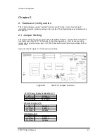
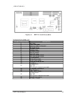
Users can refer to Figure. 2-1 for the Jumper locations.

Figure.2-1 

3307114 

Jumper 

Location

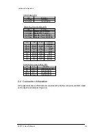
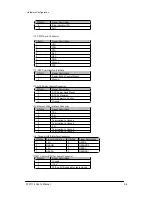
ATX/AT Power Supply Acceleration (JP1)

JP1

Function

1-3,2-4 Short

AT Power

ê

3-5,4-6 Short

ATW Power

Ethernet Function (JP2)

JP2

Function

1-2 Short

Enable

ê

1-2 Open

Disable

PS/2 Mouse (JP3)

JP3

Function

1-2 Short

Enable

ê

2-3 Short

Disable

3307114 User’s Manual

2-1

Summary of Contents for 3307114

Page 1: ...User s Manual Version 1 0 2004 Single Board Computer 3307114...

Page 2: ...uch damages The manufacturer keeps the rights in the subject to change the contents of this manual without prior notices in order to improve the function design performance quality and reliability The...

Page 3: ...performance and advanced LAN system but also for CTI application Its proprietary PCI extension connector provides an easy way to add additional function like U160 SCSI or 2nd LAN in minutes The compa...

Page 4: ...backplane connection One 4 pin ATX power control cable for backplane connection One CD Title 3307114 to support VIA PLE133 High performance graphic device driver Cost effective Realtek LAN device driv...

Page 5: ...ium III processor Chipset l VIA PLE133 Chipset Bus Interface l Follow PICMG 1 0 Revision 2 0 standard 32 bit PCI and 16 bit ISA l Fully complies with PCI Local Bus specification V2 1 support 4 master...

Page 6: ...pin shrouded connector for PS 2 mouse keyboard connection through Y Cable and backplane connection ATX Power Control Interface l One 4 pin header to support ATX power control with Modem Ring On and W...

Page 7: ...ive power connectors to enhance power driving CPU Cooling Fan l Support two 3 pin headers with wafer System Monitoring Feature l Monitor CPU system voltage CPU fan speed and system temperature Bracket...

Page 8: ...interface Besides RTL8139C Fast Ethernet controller provides a competitive fast Ethernet function The CPU socket adopts the Socket 370 type to support high availability reliability and easy operation...

Page 9: ...tment made aims to let users customize 3307114 s features In the following sections short means covering a jumper cap over jumper pins open or NC Not Connected means removing a jumper cap from jumper...

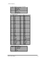
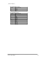
Page 10: ...terval Short Short Short 0 5 Sec Short Short NC 1 Sec Short NC Short 2 Sec Short NC NC 4 Sec NC Short Short 8 Sec NC Short NC 16 Sec NC NC Short 32 Sec NC NC NC 64 Sec DiskOnChip Jumper Setting JP6 1...

Page 11: ...rial Port 2x5 shrouded connector J11 Serial Port 2x5 shrouded connector J12 CPLD 8 pin connector J13 ATX Power Button Interface J14 ATX power control connector J15 Ethernet RJ 45 Interface connector J...

Page 12: ...scription 1 5V 470 ohm pull up for HDD LED 2 HDD Active LED cathode terminal J5 J7 IDE1 IDE2 Interface Connector PIN No Signal Description PIN No Signal Description 1 RESET 2 Ground 3 Data 7 4 Data 8...

Page 13: ...o Signal Description PIN No Signal Description 1 Strobe 14 Auto Form Feed 2 Data 0 15 Error 3 Data 1 16 Initialization 4 Data 2 17 Printer Select IN 5 Data 3 18 Ground 6 Data 4 19 Ground 7 Data 5 20 G...

Page 14: ...r Good Signal 2 ATX 5V Stand by 3 ATX Power On Control 4 Ground J15 Ethernet RJ 45 Interface Connector PIN No Signal Description 1 TX 2 TX 3 RX 4 Termination to Ground 5 Termination to Ground 6 RX 7 T...

Page 15: ...GND 21 VCC 22 AD16 23 AD17 24 AD18 25 AD19 26 AD20 27 AD21 28 AD22 29 AD23 30 GND 31 VCC 32 AD24 33 AD25 34 AD26 35 AD27 36 AD28 37 AD29 38 AD30 39 AD31 40 GND 41 VCC 42 BE 0 43 BE 1 44 BE 2 45 BE 3 4...

Page 16: ...nector PIN No Signal Description 1 12V 2 GND 3 GND 4 5V J23 VGA DSUB 15 Connector PIN No Signal Description 1 R 2 G 3 B 4 N C 5 Ground 6 Ground 7 Ground 8 Ground 9 N C 10 Ground 11 N C 12 MONID1 13 HS...

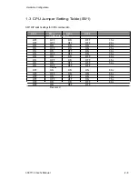
Page 17: ...O OFF OFF ON OFF 1 5x OFF OFF OFF OFF 2 0x ON ON ON ON 2 0x ON OFF ON ON 2 5x ON ON OFF ON 3 0x ON OFF OFF ON 3 5x ON ON ON OFF 4 0x ON OFF ON OFF 4 5x ON ON OFF OFF 5 0x ON OFF OFF OFF 5 5x OFF ON ON...

Page 18: ...e If this operation is not easy or smooth don t do it forcibly You need to check and rebuild the CPU pin uniformly 3 Push down the lever to lock processor chip into the socket 4 Follow the installatio...

Page 19: ...ing DIMM in any one of the DIMM sockets is allowed You can install different size of DRAM module on DIMM1 DIMM2 DIMM3 or all to make the system boot Watch out the contact and lock integrity of memory...

Page 20: ...ket Make sure that the notched corner or dot mark pin 1 of DOC corresponds to notched corner of the socket Then press the DOC gently until it fits into place If installation procedure is correct the F...

Page 21: ...ystem might be unstable or do not work due to bad contact of golden finger and ISA bus slot It is recommended to apply 4 pin 5 1 4 IDE device power connectors from your power supply onto J22 to ensure...

Page 22: ...pport Please find VIA PLE133 driver in the 3307114 CD title Drivers support Windows 3 1 Windows 95 98 98SE Windows NT 3 51 4 0 Windows 2000 OS2 and Linux 1 Windows 95 Please bring up the Display Contr...

Page 23: ...ndicator for LAN status ROBO 679 provides three LED indicators to report 82801BA MAC Fast Ethernet interfaces status Please refer to the table below as a quick reference guide RTL8139 C Name of LED Op...

Page 24: ...Clear function users must turn off the system move JP4 jumper to 2 3 position To clear CMOS please turn the power back on and turn it off again for AT system or press the toggle switch a few times fo...

Page 25: ...abort the start up 4 1 Entering Setup Turn on or reboot the computer When the message Hit DEL if you want to run SETUP appears press Del key immediately to enter BIOS setup program If the message dis...

Page 26: ...eturn to Main Menu F1 key General help on Setup navigation keys F10 key Save all the CMOS changes and exit 4 2 Main Menu Once you enter 3307114 AMI BIOS CMOS Setup Utility you should start with the Ma...

Page 27: ...OS Setup Information Standard CMOS Setup for changing time date hard disk type etc NOTE It is strongly recommended to reload Optimal Setting if CMOS is lost or BIOS is updated 3307114 User s Manual 4...

Page 28: ...e Time Drive type and Boot Sector Virus Protection Status n Screen shot AMIBIOS SETUP STANDARD CMOS SETUP C 2000 America Megatrends Inc All Rights Reserved Date mm dd yyyy Mon Oct 2 1999 Time hh mm ss...

Page 29: ...itable it in Auto for automatic item detection Sec Slave Select a suitable item or keep Press PgUp or PgDn to select a suitable it in Auto for automatic item detection Advanced CMOS Setup This setup r...

Page 30: ...bled System BIOS Cacheable Enabled Disabled C000 32K Shadow Cached Cached Enabled Disabled C800 16K Shadow Cached Cached Enabled Disabled CC00 16K Shadow Cached Cached Enabled Disabled D000 16K Shadow...

Page 31: ...tup Items Optimal Default Failsafe Default Other Options IRQ7 Monitor Ignore Ignore IRQ9 Ignore Ignore Monitor IRQ10 Ignore Ignore Monitor IRQ11 Ignore Ignore Monitor IRQ13 Ignore Ignore Monitor IRQ14...

Page 32: ...2 IRQ Priority Auto Auto 3 4 5 7 9 10 11 PCI Slot3 IRQ Priority Auto Auto 3 4 5 7 9 10 11 PCI Slot4 IRQ Priority Auto Auto 3 4 5 7 9 10 11 DMA Channel 0 PnP Pnp ISA EISA DMA Channel 1 PnP Pnp ISA EISA...

Page 33: ...rst boot device S M A R T for Hard Disks Self Monitoring analysis and reporting Technology For prediction of device degradation and or faults Boot Up Num Lock Select On to enable numeric function of t...

Page 34: ...option to Yes to support OS 2 environment L1 Cache This option controls to turn on or off the CPU s Level 1 built in cache L2 Cache Enables this option to turn on or off the CPU s Level 2 built in cac...

Page 35: ...may follow serial presence from EEPROM content by setting this option to Enabled and all of SDRAM timing options will be not available and hidden DRAM Frequency PC 100 means the memory bus is running...

Page 36: ...le power management function and effective based on following parameter settings Video Power Down Mode This option specifies the power conserving state that the VESA VGA video subsystem enters after t...

Page 37: ...y and Suspend timeout timers if activity occurs on the specified IRQ lines If set to Ignore video display monitor activity is not monitored IRQ Active When set to Monitor these options enable event mo...

Page 38: ...tem by pressing power button toggle switch directly This feature is only available on system with ATX power control interface If you use standard AT power supply this option will be ignored However ch...

Page 39: ...BIOS Setup Information lRTC Alarm Date lRTC Alarm Hour l RTC Alarm Minute lRTC Alarm Second 3307114 User s Manual 4 15...

Page 40: ...Set this option to No if the operating system such as DOS OS 2 Windows 3 x does not use PnP You must set this option correctly or PnP aware adapter cards installed in your computer will not be config...

Page 41: ...ed INTA INTB INTC INTD or Hardwired for installing off board non compliant PCI IDE card PCI Slot 1 2 3 4 IRQ Priority These options specify the priority IRQ to be used for any PCI devices installed in...

Page 42: ...d Serial Port 1 Port 2 Auto cannot set serial I O resources by manual operation Disabled indicates onboard COM port function is ineffective 3F8h COM1 assign I O address 3F8h to COM1 2F8h COM2 assign I...

Page 43: ...trol all of LPT port I O resources Disabled onboard parallel port function is ineffective and N A 378h locate IRQ7 for this default I O address 278h assign this I O address to LPT1 3BCh assign this I...

Page 44: ...POST checkpoint codes are accessible via the Manufacturing Test Port I O port 80h Whenever a recoverable error occurs during the POST the system BIOS will display an error message describing the mess...

Page 45: ...is copied to segment 0 and control will betransferred to segment 0 D6 Control is in segment 0 Next checking if Ctrl Home was pressed and verifying the system BIOS checksum If either Ctrl Home was pre...

Page 46: ...hex codes are listed in order of execution These codes are uncompressed in F0000h shadow RAM Code Description 03 The NMI is disabled Next checking for a soft reset or a power on condition 05 The BIOS...

Page 47: ...GA VGA controller is not found performing the display memory read write test next 2F EGA VGA not found Display memory R W test about to begin 30 Display memory R W test passed Look for retrace checkin...

Page 48: ...d initialized Saving the memory size information next 53 The memory size information and the CPU registers are saved Entering real mode next 54 Shutdown was successful The CPU is in real mode Disablin...

Page 49: ...ation before the C800 adaptor ROM gains control has completed The adaptor ROM check is next 98 The adaptor ROM had control and has now returned control to BIOS POST Performing any required processing...

Page 50: ...ble if necessary AC Uncompressing the DMI data and initializing DMI POST next B0 The system configuration is displayed B1 Copying any code to specific areas 00 Code copying to specific areas is done P...

Page 51: ...hrough its ATX power control connector J14 This ATX power interface can be connected to a supported backplane Such a backpane is required to have a 4 pin connector for feeding the ATX power to 3307114...

Page 52: ...o the backplane By switching your ATX power on the system goes into power standby Clicking your 3307114 ATX power button should successfully turn the system on NOTE When AT power supply is the system...

Page 53: ...e to contact with us We will do our best to support your products projects and business Address Global American Inc 17 Hampshire Drive Hudson NH 03051 Telephone Toll Free U S Only 800 833 8999 603 886...

Reviews: