3.17 CMOS Data Clear
The 3301320 provides a setting for the selection of the Clear CMOS by
J9
setting as following:
z
J9: Clear CMOS
Options Settings
Normal Operation (default)
Short 1-2
Clear CMOS
Short 2-3
1
2
3
IMPORTANT:
Before you turn on the power of your system, please
set J9 to Short 1-2 for normal operation.
3.18 Front Panel Connector
The front panel connector,
J1
, provides a multi port connection to
various functions/indicators like reset button, EXT SMI switch, speaker,
and HDD LED.
z
J1: Front Panel Connector
PIN Description
PIN Description
1
RST_SW
2
GND
2
8
3
EXT SMI
4
GND
5
SPK
6
VCC
1
7
7
HDD LED
8
With 330
pull VCC
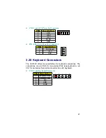
3.19 Power and Fan Connectors
3301320 provides a 5-pin ATX Power Connector at
CN2,
and two FAN
connectors at locations
FN1
and
FN2
.
z
J2: 2-pin ATX Power Switch
PIN Description
1
PW_BN
2
1
2
GND
20


