- 5 -
Cable color
Pin
Internation code
Brown
Live
L
Blue
Neutral
N
Yellow / Green
Earth
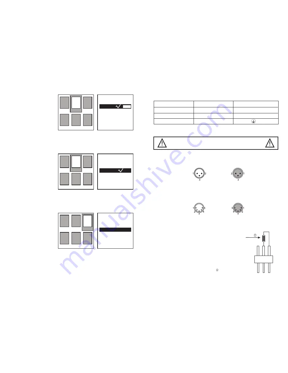
connection cables is as below:
The earth has to be connected.
4. Master-slave / DMX 512 connection
Only use a stereo shielded cable and 3-pin XLR-plugs and connectors in order to
connect the controller with the fixture or one fixture with another.
If you are using controllers with this occupation, you can connect the DMX-output of
the controller directly with the DMX-input of the 1st device in the DMX-chain. If you
wish to connect DMX-controllers with other XLR-outputs, you need to use adapter-
cables.
For Master-slave connection, you need to set a device as
the Master device. All other devices will be the slave devices.
Connect the DMX-output of the first device (Master) in the
chain with the DMX-input of the second device (the first
slave device). Connect the DMX-output of the second de-
vice (the first slave device) with the DMX-input of the third
device (the second slave device). Always connect one
output with the input of the next device until all devices
are connected.
At the last device, the DMX-cable has to be
terminated with a terminator. Solder a 120
resistor
between Data(-) and Data(+) into a 3-pin XLR-plug and
plug it in the DMX-output of the last device.
Occupation of the XLR-connection:
Building a serial Master-slave / DMX-chain:
Caution:
The wires must not come into contact with each other, otherwise
the fixtures will not work at all, or will not work properly.
DMX input
XLR mounting
socket
DMX input
XLR mounting
socket
DMX output
XLR mounting
socket
DMX output
XLR mounting
socket
1=Ground
2=Data (-)
3=Data (+)
1=Ground
2=Data (-)
3=Data (+)
4: no use
5: no use
120
PIN 3
PIN 1
PIN 2
- 8 -
DJJ
You will see the image on the
right.
Press the Up or Down button to
select the Auto mode.
Press the Enter button, you
will see Auto1 - Auto8 on the
right. This is the 8 built-in
programs for auto operation.
Press the Enter button, the
Auto1 - Auto8 will be
highlighted.
Press the Up or Down button to
select one of the 8 programs.
Press the Enter button to save your setting.
Press the Menu button to exit to the main menu.
Press the Menu button to back
to the main menu.
Press the Menu button once
again, you will see one of the
6 icons will be highlighted.
Press Up or Down button to
select the second icon on the
first line.
Press the Enter button.
You will see the image on the
right.
Press the Up or Down button to select the Sound mode.
Press the Enter button to save your setting.
Press the Menu button to exit to the main menu.
Press the Menu button to back
to the main menu.
Press the Menu button once
again, you will see one of the
6 icons will be highlighted.
Press Up or Down button to
select the third icon on the
first line.
Press the Enter button.
You will see the image on the
right. There are 6 selections,
Pan, Tilt, Red. Green, Blue and White.
Press the Up or Down button to select one of the 6 selections.
Press the Enter button, you will see XXX on the right will be highlighted. This is a
figure between 000 and 255.
Press the Up or Down button to select one of the 000 - 255.
Press the Enter button to save your setting.
Press the Menu button to exit to the main menu.
Sound-activated operation
Test mode
Auto
Auto
Tilt
155
Blue
155
Address
Address
Address
RunMode
RunMode
RunMode
SetUp
SetUp
SetUp
TestMode
TestMode
TestMode
SysInfo
SysInfo
SysInfo
RunMode
RunMode
TestMode
Language
Language
Language
DMX
DMX
Pan
255
Green
000
Sound
Sound
Red
255
White
200
Auto1


