background image

12

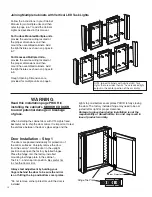
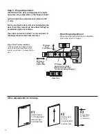
Joining Multiple Cabinets with Vertical LED Task Lights

Follow the instructions in your Cabinet
Manual to join multiple units and then
refer to page 6 & 7 to add the Vertical
Lights as described in this manual.

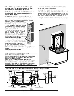
For Surface Mounted Multiple units

provide the service wiring located at
the proper dimensions and then
mount the assembled cabinets. Add
the light fixtures as shown on pages 6
& 7.

For Recessed Multiple Units--

provide the service wiring located at
the proper dimensions and then
mount the assembled cabinets. Add
the light fixtures as shown on pages 8
& 9.

Rough Opening Dimensions are 
provided for multiple units on page 5.

NOTE: Joined Cabinets with Vertical LED Task
Lights that are wider than 32” have reduced light
output in the center portion of the assembly.

Hinge Toe Plate 

Corner Protectors

Door Installation -- Step 1

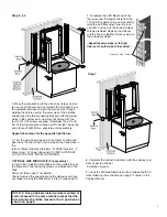
The doors are packed individually for protection of
the mirror surfaces. Carefully remove the door
from the carton.* Hold the door in the upright 
position snap open the factory installed hinges.
Place the hinge onto the factory-installed 
mounting toe/hinge plate in the cabinet -- 
Toe first -- and snap into position. Be careful not
to chip the door mirror.

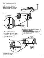
Always test adjustment by holding your 
fingers behind the door to be sure the mirror
is not hitting the top and bottom cover plates.

*Do 


not remove corner protectors until the door is 

installed

WARNIN

G

Read this installation page PRIOR to 
installing the cabinet’s MIRRORED DOOR 
to avoid potential damage or breakage 
of glass. 

When installing the cabinet door with VTL Lights fixed,
becareful not to chip the door mirror. It is important to test
the distance between the door’s glass edge and the

light’s top and bottom cover plates PRIOR to fully closing
the door. The factory installed hinge may need to be ad-
justed left or right for proper clearance. 

Damage to glass door during installation is not the
responsibility of GlassCrafters Inc. and may result in
loss of product warranty.

Summary of Contents for GC1624

Page 1: ...e following instruction sheets are applicable for installation of this accessory on all Flat or Beveled Frameless Mirror Cabinets both 4 deep and 6 deep This accessory also may be added to any previou...

Page 2: ...of electric shock 1 Turn Power off at service panel before working on wiring 2 DO NOT SPRAY LIQUID CLEANERS on the Vertical LED Task Light For cleaning we recommend using ammonia free Sprayway brand...

Page 3: ...Installation Wood Screw 4 10 31 Screws 8 Left Not to Scale Each pair of lights ships with one parts package Right Not to Scale Includes Wire Bushing Top Bottom Plate Cover Screw Guide Installation Par...

Page 4: ...led wiring or any of its features or appurte nances 4 This unit s service wiring and electrical connections must be made by a Licensed Electrician in a manner that conforms to the National Electric Co...

Page 5: ...ire for pull through RECESSED MOUNT Important Make sure you allow for a minimum of 1 clearance above any obstruction such as faucets etc Avoid installing light fixtures too close to sinks RECESSED MOU...

Page 6: ...om plates with the two screws located in the rectangular part of the plates Remove the acrylic diffuser by squeezing from the narrow side and pivoting it away from the fixture Unscrew the three flathe...

Page 7: ...2 Side Mirror Brackets on the outside face of the Mounting Panel using the screws and Brackets in the Side Mirror Kit See page 11 for details Do not remove the paper covering the adhesive until you a...

Page 8: ...h the two screws located in the rectangular part of the plates Remove the acrylic diffuser by squeezing from the narrow side and pivoting it away from the fixture Unscrew the three flathead stainless...

Page 9: ...Move the wire bushing to the wire entry holes you plan to use Insert the service wire through the wire bushing at the selected locations and pull the service wire through c Trim the wire cable leavin...

Page 10: ...pending the Electrician s wiring plan this allows a through wire connection for the secparate 20A GFCI circuit for the E O cabinet to go through a Light Fixture and into the shelf The Service to the C...

Page 11: ...of the side mirror kit panel with the Alcohol pads Check alignment before you attach the mirror to be sure it will align even with the top of the cabinet 8 Peel off paper covering of the adhesive tap...

Page 12: ...f the mirror surfaces Carefully remove the door from the carton Hold the door in the upright position snap open the factory installed hinges Place the hinge onto the factory installed mounting toe hin...

Page 13: ...lace Step 2 Test Door Clearance Door Installation continued CAUTION Always test by closing the door with your hand behing the door to test door clearance and determine if any adjustment is needed to a...

Page 14: ...e as shown Left and right hinge adjustment is limited to 1 32 1 mm Test by closing the door with your hand behing the door to test the clearance to avoid door hitting Top and Bottom Light Cover Plates...

Page 15: ...w This will eliminate the possibility of the door hitting a wall sconce or other decorative items Special adjustments of these clips is required with the Vertical Light Mirrored Cabinet Use caution wh...

Page 16: ...installation or if the reported defects are a result of faulty installation abuse misuse abnormal wear poor maintenance accident or repairs by service personnel other than the original professional in...

Reviews: