


1
3
2
14
Swiss Lifting Solutions
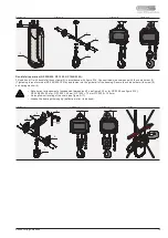
Figure 2-7
Figure 2-8
Figure 2-9
Chain end:
The chain end is to be fixed to the housing in accordance with figure 2-7 or figure 2-8 and the limit stop in accordance with figure 2-9.
Ensure that the end of the chain is not twisted. The section of chain after the limit stop (1) must be adjusted to the height of the chain
container. Here, the length of the chain section must be selected such that the limit stop lies on the floor of the container when the chain is
pulled into it (see figure 2-10).
1 fall operation:
The load hook (1) is connected to the chain with a single fall hook clamp (2). For the power transmission, the mounting of the bolt (3) is
important (see figure 2-11).
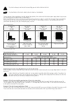
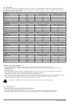
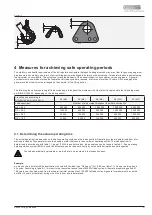
• Note correct arrangement of suspension (dimension k1, see figure 2-12 or for GP 2500 see figure 2-13):
GPM 250 = symmetrical, GP 250/500 = 41 mm, GP 1000 = 43 mm, GP 1600 = 53 mm, GP 2500 = 87 mm.
• Grease the bearings thoroughly (load hook).
Figure 2-6
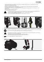
2.2.2 Load chain
• Only use original chains.
• Welding seam of the chain links must face inward on the chain wheel (see figure 2-6).
• The geared limit switch must be mechanically deactivated for pulling in the chain, see chapter 2.2.3.
Before start-up and during operation, the load chain must be oiled along its full length. Oil must constantly be present on the internal,
contacting and rubbing surfaces of the chain links. Lubrication is carried out by submersion or with an oil can, using a creeping gear oil
(GIS chain oil or SAE 15W-40). The end of the chain (1) should be attached to a flexible piece of wire or chain pulling loop (2) and fed
through the chain wheel (3) of the electric chain hoist. Through short switching impulses, the chain will be pulled in correctly in
accordance with figure 2-6. The lifting height must be adjusted such that the hook fittings lie on the ground in the lowest hook position.


