


- 29 -
Hardware Installation
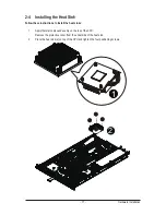
3-3 Front Panel LED and Buttons
No. Name
Color
Status
Description
1.
Power button
and LED
Green
On
System has power applied to itor ACPI S0 state
Green
Blink
System is in ACPI S1 state (sleep mode)
N/A
Off
System is not powered on or in ACPI S5 state
(power off)
System is in ACPI S4 state (hlbernate mode)
2.
ID button
and LED
Blue
On
System identification is active
N/A
Off
System identification is disabled
3.
System
Status LED
Green
On
Running or normal peration.
Amber
On
There’s at least one sensor that has critical alert..
N/A
Off
System not ready
4.
HDD Status
LED
Green
On
HDD access
N/A
Off
Idle
5.
LAN 2 LED
Green
On
Link between system and network or no access
Green
Blink
Network access
6.
LAN 1 LED
Green
On
Link between system and network or no access
Green
Blink
Network access
7.
Reset button
8.
NMI button
1
2
3
4
5
6
7
8
Summary of Contents for GS-R12PE
Page 46: ...BIOS Setup 46 5 2 3 CPU Configuration ...
Page 47: ... 47 BIOS Setup ...
Page 53: ... 53 BIOS Setup 5 2 6 Serial Port Console Redirection ...
Page 56: ...BIOS Setup 56 5 3 1 North Bridge Configuration ...
Page 57: ... 57 BIOS Setup 5 3 1 1 IOH Configuration ...
Page 60: ...BIOS Setup 60 5 3 1 2 DIMM Information ...
Page 74: ...BIOS Setup 74 4 Boot into BIOS recovery 5 Run Proceed with flash update 6 BIOS updated ...


