background image

Appendix

- 120 -

Step 3:
The 

BGA Rebuild

 item in the 

Information

 block will display the current rebuild progress. After the rebuild is 

complete, the 

Status

 will display as 

Functional

. Please note the rebuild will be stopped if you exit the rebuild 

screen before the rebuild is complete.  

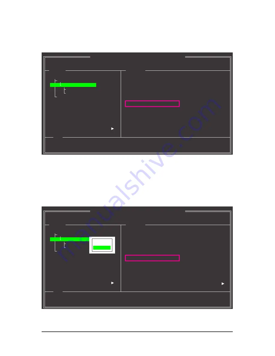
Resume the Stopped Rebuild Process

To resume the stopped rebuild process, enter the 

GSATA RAID Configuration

 menu in BIOS Setup again. 

Move the selection bar to the array to be rebuilt (for example, VD 0: New_VD). Press <Enter> on this array 
and select 

Resume

. Press <Enter> again to continue the rebuild process. Note that the percentage of the last 

rebuild progress will be rounded down to the nearest multiple of 10 percent (as shown in the 

BGA Rebuild


item). For example, if you stopped the rebuild at 27%, the rebuild will continue at 20%. 

Marvell BIOS Setup (c) 2009 Marvell Technology Group Ltd.

Topology 

Information

Help

ID  


0

Name   


New_VD

Status   


Degrade

Stripe Size 


64K

RAID Mode   

RAID1

Size 


75776MB

BGA Status   

Running

BGA Rebuild   

27%

Number of PDs 

2

Numbers  


0 8

HBA  0 :   Marvell 0

     Virtual Disks


VD 0: New_VD


   PD 0: WDC WD800JD-22L

           PD 8: WDC WD800JD-22L


Free Physical Disks

Virtual Disk: A set of disk blocks presented to an operating environment as 

a range of consecutively numbered logical blocks with disk-like storage.

ENTER:  Operation    F10:  Exit/Save    ESC:  Return 


Marvell BIOS Setup (c) 2009 Marvell Technology Group Ltd.

Topology 

Information

Help

ID  


0

Name   


New_VD

Status   


Degrade

Stripe Size 


64K

RAID Mode   

RAID1

Size 


75776MB

BGA Status   

Running

BGA Rebuild   

20%

Number of PDs 

2

Numbers  


0 8

HBA  0 :   Marvell 0

     Virtual Disks


VD 0: New_VD


   PD 0: WDC WD800JD-22L

           PD 8: WDC WD800JD-22L


Free Physical Disks

Virtual Disk: A set of disk blocks presented to an operating environment as 

a range of consecutively numbered logical blocks with disk-like storage.

ENTER:  Operation    F10:  Exit/Save    ESC:  Return 


[Delete]

[Resume]

Summary of Contents for GA-P55A-UD5

Page 1: ...GA P55A UD5 LGA1156 socket motherboard for Intel Core i7 processor family Intel Core i5 processor family User s Manual Rev 1002 12ME P55AUD5 1002R...

Page 2: ...Motherboard GA P55A UD5 Oct 16 2009 Oct 16 2009 Motherboard GA P55A UD5...

Page 3: ...seofthisproduct GIGABYTEprovidesthefollowingtypesofdocumentations For quick set up of the product read the Quick Installation Guide included with the product For detailed product information carefully...

Page 4: ...stalling an Expansion Card 18 1 6 Setup of ATI CrossFireX NVIDIA SLI Configuration 19 1 7 Back Panel Connectors 20 1 8 Onboard LEDs and Buttons 22 1 9 Internal Connectors 24 Chapter 2 BIOS Setup 35 2...

Page 5: ...10 Teaming 86 Chapter 5 Appendix 87 5 1 Configuring SATA Hard Drive s 87 5 1 1 Configuring Intel P55 SATA Controllers 87 5 1 2 Configuring JMicron JMB362 SATA Controller 95 5 1 3 Configuring Marvell...

Page 6: ...2 port USB 2 0 bracket Part No 12CR1 1UB030 5 R 2 port IEEE 1394a bracket Part No 12CF1 1IE008 0 R 2 port SATA power cable Part No 12CF1 2SERPW 0 R S PDIF In cable Part No 12CR1 1SPDIN 0 R COM port c...

Page 7: ...SPDIF_I DDR3_2 DDR3_1 DDR3_4 DDR3_3 BAT F_PANEL COMA IT8720 ATX_12V_2X Intel P55 FDD SATA2_1 SATA2_3 SATA2_5 GSATA3_7 SATA2_0 SATA2_2 SATA2_4 GSATA3_6 PCI1 PCI2 CODEC PWR_FAN PCH_FAN SYS_FAN1 B_BIOS...

Page 8: ...ess Bus IT8720 Floppy CPU CLK 133 MHz 6 SATA 3Gb s 1 PCI Express x16 Dual BIOS COM Port 12 USB 2 0 1 1 LPC Bus TSB43AB23 3 IEEE 1394a DDR3 2200 1333 1066 800 MHz Dual Channel Memory 2 PCI Express x8 P...

Page 9: ...and first touch a metal object to eliminate static electricity Prior to installing the motherboard please have it on top of an antistatic pad or within an electrostatic shielding container Before unp...

Page 10: ...s 1 x PCI Express x16 slot running at x16 PCIEX16_1 Note 2 1 x PCI Express x16 slot running at x8 PCIEX8_1 Note 3 The PCIEX16_1 and PCIEX8_1 slots conform to PCI Express 2 0 standard 1 x PCI Express x...

Page 11: ...Gb s connectors w 1 x CPU fan header w 3 x system fan headers w 1 x power fan header w 1 x Chipset fan header w 1 x front panel header w 1 x front panel audio header w 1 x CD In connector w 1 x S PDIF...

Page 12: ...ontrol function is supported will depend on the CPU system cooler you install Note 6 Available functions in EasyTune may differ by motherboard model Note 7 This feature is optional due to different re...

Page 13: ...revent hardware damage Locate the pin one of the CPU The CPU cannot be inserted if oriented incorrectly Or you may locate the notches on both sides of the CPU and alignment keys on the CPU socket Appl...

Page 14: ...keys and gently insert the CPU into position Step 5 Push the CPU socket lever back into its locked position Step 4 Once the CPU is properly inserted use one hand to hold the socket lever and use the o...

Page 15: ...Step 3 Place the cooler atop the CPU aligning the four push pins through the pin holes on the mother board Push down on the push pins diagonally Step 4 You should hear a click when pushing down each...

Page 16: ...unplug the power cord from the power outlet before installing the memory to prevent hardware damage Memory modules have a foolproof design A memory module can be installed in only one direc tion If yo...

Page 17: ...on the socket As indicated in the picture on the left place your fin gers on the top edge of the memory push down on the memory and insert it vertically into the memory socket Step 2 The clips at both...

Page 18: ...s metal bracket to the chassis back panel with a screw 5 After installing all expansion cards replace the chassis cover s 6 Turn on your computer If necessary go to BIOS Setup to make any required BIO...

Page 19: ...he CrossFire Note SLI bridge connectors in the CrossFireX SLI gold edge connectors on top of the two cards Step 3 Plug the display cable into the graphics card on the PCIEX16_1 slot C Configuring the...

Page 20: ...nnector provides digital audio out to an external audio system that supports digital coaxial audio Before using this feature ensure that your audio system provides a coaxial digital audio in connector...

Page 21: ...4 5 1 7 1 channel audio configuration Line In Jack Blue The default line in jack Use this audio jack for line in devices such as an optical drive walkman etc Line Out Jack Green The default line out j...

Page 22: ...ACPI LEDs indicate the system power status S0 S1 S3 S4 S5 to prevent potential hard ware damage due to improper plug unplug actions ACPI LEDs S4_S5_LED S3_LED S1_LED S0_LED CPU VTT Memory Phase Indica...

Page 23: ...actory defaults when needed PW_SW Power button RST_SW Reset button CMOS_SW Clearing CMOS button Always turn off your computer and unplug the power cord from the power outlet before clear ing the CMOS...

Page 24: ...g the power cord from the power outlet to prevent damage to the devices After installing the device and before turning on the computer make sure the device cable has been securely attached to the conn...

Page 25: ...supplies power to the CPU If the 12V power connector is not connected the computer will not start Use of a power supply providing a 2x4 12V power connector is recommended by the CPU manufacturer when...

Page 26: ...Chipset and system from overheating Overheating may result in damage to the CPU Chipset or the system may hang These fan headers are not configuration jumper blocks Do not place a jumper cap on the h...

Page 27: ...about configuring master slave settings for the IDE devices read the instructions from the device manufacturers 2 40 1 39 7 FDD Floppy Disk Drive Connector This connector is used to connect a floppy d...

Page 28: ...nd are compatible with SATA 3Gb s and SATA 1 5Gb s standards Each SATA connector supports a single SATA device The Marvell 9128 supports RAID 0 and RAID 1 Refer to Chapter 5 Configuring SATA Hard Driv...

Page 29: ...r writing data RES Reset Switch Green Connects to the reset switch on the chassis front panel Press the reset switch to restart the computer if the computer freezes and fails to perform a normal resta...

Page 30: ...0 The front panel audio header supports HD audio by default If your chassis provides an AC 97 front panel audio module refer to the instructions on how to activate AC 97 functionality via the audio so...

Page 31: ...gital S PDIF Out and connects a S PDIF digital audio cable provided by expan sion cards for digital audio output from your motherboard to certain expansion cards like graphics cards and sound cards Fo...

Page 32: ...USB DY 7 GND 8 GND 9 No Pin 10 NC Pin No Definition 1 TPA 2 TPA 3 GND 4 GND 5 TPB 6 TPB 7 Power 12V 8 Power 12V 9 No Pin 10 GND Do not plug the IEEE 1394 bracket 2x5 pin cable into the USB header Prio...

Page 33: ...lug the power cord 2 Gently remove the battery from the battery holder and wait for one minute Or use a metal object like a screwdriver to touch the positive and negative terminals of the battery hold...

Page 34: ...34 Hardware Installation...

Page 35: ...BIOS without entering the operating system BIOS is a Windows based utility that searches and downloads the latest version of BIOS from the Internet and updates the BIOS For instructions on using the Q...

Page 36: ...enu allows you to set the first boot device without entering BIOS Setup In Boot Menu use the up arrow key h or the down arrow key i to select the first boot device then press Enter to accept To exit B...

Page 37: ...menus only F5 Restore the previous BIOS settings for the current submenus F6 Load the Fail Safe BIOS default settings for the current submenus F7 Load the Optimized BIOS default settings for the curre...

Page 38: ...is menu to configure all peripheral devices such as IDE SATA USB integrated audio and inte grated LAN etc Power Management Setup Use this menu to configure all the power saving functions PC Health Sta...

Page 39: ...ion D1 BCLK 133 27 MHz CPU Frequency 3198 42 MHz Memory Frequency 1332 80 MHz Total Memory Size 1024 MB CPU Temperature 45o C PCH Temperature 40o C Vcore 1 264V DRAM Voltage 1 584V Move Enter Select P...

Page 40: ...ote Auto Bi Directional PROCHOT Note Auto Advanced CPU Core Features Intel R Turbo Boost Tech Allows you to determine whether to enable the Intel CPU Turbo Boost technology Auto lets the BIOS automati...

Page 41: ...ote Auto Lets the BIOS automatically configure this setting Default Enabled When the CPU or chipset detects that an overheating is occurring PROCHOT signals will be emitted to lower CPU performance to...

Page 42: ...ng power to maximize system performance C I A 2 allows your system bus to be changed dynamically based on CPU loading through the use of 5 preset states Note System stability varies depending on your...

Page 43: ...Profile1 Uses Profile 1 settings Profile2 Note Uses Profile 2 settings System Memory Multiplier SPD Allows you to set the system memory multiplier Auto sets memory multiplier according to memory SPD d...

Page 44: ...Auto x tRP 7 Auto x tRAS 20 Auto Channel AAdvanced Timing Control x tRC 28 Auto x tRRD 4 Auto x tWTR 5 Auto x tWR 10 Auto x tWTP 21 Auto x tWL 7 Auto x tRFC 60 Auto x tRTP 5 Auto x tFAW 16 Auto x Comm...

Page 45: ...10 tRFC Options are Auto default 1 255 tRTP Options are Auto default 1 15 tFAW Options are Auto default 1 63 Command Rate CMD Options are Auto default 1 3 Channel A B Misc Timing Control B2B CAS Delay...

Page 46: ...5 Auto x On The Same Rank 1 Auto Channel A Writes Followed by Writes x Different DIMMs 6 Auto x Different Ranks 6 Auto x On The Same Rank 1 Auto Channel A B Turnaround Settings Channel A B Reads Foll...

Page 47: ...sables Load Line Calibration This item allows you to adjust Vdroop at different levels En abling Load Line Calibration may keep the CPU voltage more constant under light and heavy CPU load Standard Di...

Page 48: ...Default Enabled This section provides information on the BIOS version CPU base clock CPU frequency memory frequency total memory size CPU temperature Chipset temperature Vcore and memory voltage CMOS...

Page 49: ...s Date mm dd yy Fri May 22 2009 Time hh mm ss 22 31 24 IDE Channel 0 Master None IDE Channel 0 Slave None IDE Channel 1 Master None IDE Channel 1 Slave None IDE Channel 2 Master None IDE Channel 3 Mas...

Page 50: ...nformation on the hard drive Capacity Approximate capacity of the currently installed hard drive Cylinder Number of cylinders Head Number of heads Precomp Write precompensation cylinder Landing Zone L...

Page 51: ...ifies whether a password is required every time the system boots or only when you enter BIOS Setup After configuring this item set the password s under the Set Supervisor User Password item in the BIO...

Page 52: ...llows you to determine whether to display the GIGABYTE Logo at system startup Disabled displays normal POST message Default Enabled Backup BIOS Image to HDD Allows the system to copy the BIOS image fi...

Page 53: ...ed PCH SATA Control Mode IDE SATA Port0 3 Native Mode Enabled USB Controllers Enabled USB Legacy Function Enabled USB Storage Function Enabled Turbo SATA3 USB3 0 Auto Azalia Codec Auto PCI Express x4...

Page 54: ...ell 9128 or NEC USB 3 0 controller to PCIe Gen 2 Please note that when only one graphics card is installed on the PCIEX16_1 slot it will operate at up to x8 mode if either one of the two controllers i...

Page 55: ...Part4 5 Status Open Length 0m Part7 8 Status Open Length 0m Move Enter Select PU PD Value F10 Save ESC Exit F1 General Help F5 Previous Values F6 Fail Safe Defaults F7 Optimized Defaults Item Help Men...

Page 56: ...tion that allows the storage driver to enable advanced Serial ATA features such as Native Command Queuing and hot plug RAID Enables RAID for the SATA controller GSATA Controller Marvell 9128 Chip GSAT...

Page 57: ...system If the power button is pressed for less than 4 seconds the system will enter suspend mode PME Event Wake Up Allows the system to be awakened from an ACPI sleep state by a wake up signal from a...

Page 58: ...k on left button on the PS 2 mouse to turn on the system Power On By Keyboard Allows the system to be turned on by a PS 2 keyboard wake up event Note you need an ATX power supply providing at least 1A...

Page 59: ...status record set Reset Case Open Status to Enabled save the settings to the CMOS and then restart your system Current Voltage V Vcore DDR15V 3 3V 5V 12V Displays the current system voltages 2 8 PC He...

Page 60: ...s or disables the CPU fan speed control function Enabled allows the CPU fan to run at different speed according to the CPU temperature You can adjust the fan speed with EasyTune based on system requir...

Page 61: ...CMOS Features Advanced BIOS Features Integrated Peripherals Power Management Setup PC Health Status Load Fail Safe Defaults ESC Quit Select Item F11 Save CMOS to BIOS F8 Q Flash F10 Save Exit Setup F1...

Page 62: ...stem startup to continue system boot In BIOS Setup you must enter the supervisor password if you wish to make changes to BIOS settings The user password only allows you to view the BIOS settings but n...

Page 63: ...nt Setup PC Health Status Load Fail Safe Defaults ESC Quit Select Item F11 Save CMOS to BIOS F8 Q Flash F10 Save Exit Setup F12 Load CMOS from BIOS Load Optimized Defaults Set Supervisor Password Set...

Page 64: ...Disables the security chip Default Security Chip State Displays the current settings in the security chip 2 14 Security Chip Configuration CMOS Setup Utility Copyright C 1984 2009 Award Software Secur...

Page 65: ...o manually select the drivers you wish to install Please ignore the popup dialog box es e g the Found New Hardware Wizard displayed when Xpress Install is installing the drivers Failure to do so may a...

Page 66: ...ties and applications that GIGABYTE develops and some free software You can click the Install button on the right of an item to install it 3 3 Technical Manuals This page provides GIGABYTE s applicati...

Page 67: ...4 Contact For the detailed contact information of the GIGABYTE Taiwan headquarter or worldwide branch offices click the URL on this page to link to the GIGABYTE website 3 5 System This page provides t...

Page 68: ...d Center button to link to the GIGABYTE website The latest version of the BIOS drivers or applications will be displayed 3 7 New Utilities This page provides a quick link to GIGABYTE s lately develope...

Page 69: ...cked up restored It takes longer to back up a hard drive than to restore it System Requirements At least 512 MB of system memory VESA compatible graphics card Windows XP with SP1 or later Windows Vist...

Page 70: ...ll save the backup file to the unallocated space black stripe along the top Please note that if there is no enough unallocated space Xpress Recovery2 cannot save the backup file B Accessing Xpress Rec...

Page 71: ...p to your hard drive in case the system breaks down The RESTORE option will not be present if no backup is created before Select REBOOT to exit Xpress Recovery2 Step 2 After the backup file is removed...

Page 72: ...process What is BIOS BIOS allows you to update the system BIOS while in the Windows environ ment BIOS will download the latest BIOS file from the nearest BIOS server site and update the BIOS 4 2 1 Up...

Page 73: ...save the current BIOS file Q Flash only supports USB flash drive or hard drives using FAT32 16 12 file system If the BIOS update file is saved to a hard drive in RAID AHCI mode or a hard drive attache...

Page 74: ...d then press Y to save settings to CMOS and exit BIOS Setup The proce dure is complete after the system restarts Press Y to load BIOS defaults CMOS Setup Utility Copyright C 1984 2009 Award Software L...

Page 75: ...atches your motherboard model Follow the on screen instructions to complete 2 Update the BIOS without Using the Internet Update Function Click Update BIOS from File then select the location where you...

Page 76: ...led memory module s You can select memory module on a specific slot to see its information The Tuner tab allows you to change system clock settings and voltages Quick Boost mode provides you with 3 le...

Page 77: ...motherboard model CPU Power and Power Scores are for reference only Actual results may vary based on testing method Meter Mode Button Information Table Button Description 1 Dynamic Energy Saver On Off...

Page 78: ...h Mode In Stealth Mode the system continues to work with the user defined power saving settings even after the system is restarted Re enter the application only if you want to make any changes or comp...

Page 79: ...n area and right click on this icon to configure the data sharing settings Note This option is available only when data sharing is NOT enabled Figure 1 Data Sharing Disabled Figure 2 Data Sharing Enab...

Page 80: ...el and restart your computer for the changes to take effect SMART QuickBoost SMART QuickBoost features quick and effortless CPU overclocking for novice and experienced users alike users simply click o...

Page 81: ...k a file folder select the file folder you wish to copy and click the Copy button Button Function Enable Enables automatic daily backup Note 3 Schedule Sets a daily backup schedule Capacity Sets the p...

Page 82: ...You can set the User Password in the system BIOS Setup program to prevent the system time being changed by other users Instructions Select the Enable check box at the bottom of the ON OFF Recorder or...

Page 83: ...dvanced mode to enter the Infineon Security Platform Settings Tool to configure advanced settings You have to at least set up a Personal Secure Drive PSD Refer to the Infineon Security Platform Help f...

Page 84: ...etermined period of time After completing the settings click Set for the settings to take effect and then click Exit to quit Configuring the Bluetooth cell phone key After you select a cell phone the...

Page 85: ...ported RAID array depending on your needs and hardware components 3 Exits the X H D utility Click Cancel to exit the X H D utility Instructions Note 2 Before launching X H D make sure the newly added...

Page 86: ...l for further details Step 3 Choose Teaming and click the Create Team button Removing the Existing Teaming Step 4 Give a name for the Team e g Teaming and set up the Teaming mode based on your hub s s...

Page 87: ...epare only one hard drive An empty formatted floppy disk Windows Vista XP setup disk Motherboard driver disk 5 1 1 Configuring Intel P55 SATA Controllers A Installing SATA hard drive s in your compute...

Page 88: ...hall depend on the motherboard you have and the BIOS version Figure 1 CMOS Setup Utility Copyright C 1984 2009 Award Software Integrated Peripherals eXtreme Hard Drive XHD Disabled PCH SATA Control Mo...

Page 89: ...Figure 3 Intel R Matrix Storage Manager option ROM v8 9 0 1023 PCH D wRAID5 Copyright C 2003 09 Intel Corporation All Rights Reserved RAID Volumes None defined Physical Disks Port Drive Model Serial...

Page 90: ...Figure 5 Intel R Matrix Storage Manager option ROM v8 9 0 1023 PCH D wRAID5 Copyright C 2003 09 Intel Corporation All Rights Reserved Choose the RAID level RAID0 Stripes data performance RAID1 Mirror...

Page 91: ...2003 09 Intel Corporation All Rights Reserved Press ENTER to create the specified volume hi Change TAB Next ESC Previous Menu ENTER Select HELP Name Volume0 RAID Level RAID0 Stripe Disks Select Disks...

Page 92: ...atrix Storage Manager option ROM v8 9 0 1023 PCH D wRAID5 Copyright C 2003 09 Intel Corporation All Rights Reserved 3 Reset Disks to Non RAID 4 Recovery Volume Options RAID Volumes None defined Physic...

Page 93: ...111 7GB Non RAID Disk R1 ST3120026AS 3JT329JX 111 7GB Non RAID Disk Select 1 Master and 1 Recovery disk to create volume Step 4 Under Sync select Continuous or On Request Figure 11 When set to Continu...

Page 94: ...Storage Manager option ROM v8 9 0 1023 PCH D wRAID5 Copyright C 2003 09 Intel Corporation All Rights Reserved Deleting a volume will reset the disks to non RAID WARNING ALL DISK DATA WILL BE DELETED T...

Page 95: ...system BIOS Setup Step 1 Turn on your computer and press Delete to enter BIOS Setup during the POST Power On Self Test Make sure eSATA Controller under the Integrated Peripherals menu is enabled Figur...

Page 96: ...ID Press Ctrl G to enter RAID Setup Utility Figure 2 In the main screen of the RAID setup utility Figure 3 use the up or down arrow key to highlight through choices in the Main Menu block Highlight th...

Page 97: ...Name GRAID_ Level 0 Stripe Disks Select Disk Block 128 KB Size 240 GB Confirm Creation Model Name Available Type Status HDD0 ST3120026AS 120 GB Non RAID HDD1 ST3120026AS 120 GB Non RAID Help fg Move...

Page 98: ...orp RAID Setup Utility v1 07 06 Name GRAID Level 0 Stripe Disks Select Disk Block 128 KB Size 240 GB Confirm Creation Model Name Available Type Status HDD0 ST3120026AS 120 GB Non RAID HDD1 ST3120026AS...

Page 99: ...the array use the Tab key while in the Main Menu block to move the selection bar to the RAID Disk Drive List block Select the array and press Enter A small window dis playing the array information wi...

Page 100: ...ID SPACE Mark Delete DEL Confirm ESC Abort RAID Disk Drive List Main Menu Hard Disk Drive List Gigabyte Technology Corp RAID Setup Utility v1 07 06 Create RAID Disk Drive Delete RAID Disk Drive Revert...

Page 101: ...1 Turn on your computer and press Delete to enter BIOS Setup during the POST Power On Self Test Make sure GSATA Controller under the Integrated Peripherals menu is enabled Then set GSATA Ctrl Mode to...

Page 102: ...Operation F10 Exit Save ESC Return Marvell BIOS Setup c 2009 Marvell Technology Group Ltd Topology Information Help Vendor ID 1B4B Device ID 91A3 Revision ID B1 BIOS Version 1 0 0 1006 Firmware Versio...

Page 103: ...BIOS Setup c 2009 Marvell Technology Group Ltd Configure Select free disksCreate Virtual Disk Help Virtual disk configurations ENTER Operation F10 Exit Save ESC Return RAID Level RAID 0 Max Size MB 15...

Page 104: ...n F10 Exit Save ESC Return 7 Save the Settings and Exit After you complete the RAID configuration and before you exit the configura tion screen be sure to press F10 in the main screen Press Y to confi...

Page 105: ...A 0 Marvell 0 Virtual Disks VD 0 New_VD PD 0 WDC WD800JD 22L PD 0 WDC WD800JD 22L Free Physical Disks Marvell RAID on chip controller ENTER Operation F10 Exit Save ESC Return Do you want to delete thi...

Page 106: ...w to copy the driver in MS DOS and Windows mode In MS DOS mode Prepare a startup disk that has CD ROM support and a blank formatted floppy disk Steps 1 Boot from the startup disk 2 Remove the startup...

Page 107: ...he controller driver by pressing the corresponding letter from the menu and press Enter For example from the menu in Figure 5 For the Intel P55 select 1 Intel Matrix Storage driver for 32bit system fo...

Page 108: ...tel P55 Insert the floppy disk containing the SATA RAID AHCI driver and press S Then a controller menu similar to Figure 2 below will appear Select Intel R ICH8R ICH9R ICH10R DO PCH SATA RAID Controll...

Page 109: ...for GIGABYTE GBB363 Controller Windows 2000 AHCI Driver for GIGABYTE GBB363 Controller Windows 2000 RAID Driver for GIGABYTE GBB360 Controller For the Marvell 9128 Insert the floppy disk containing t...

Page 110: ...loppy disk USB flash drive that contains the driver Method B then specify the location of the driver Figure 6 Note For users using a SATA optical drive be sure to copy the driver files from the mother...

Page 111: ...elect Intel R ICH8R ICH9R ICH10R DO PCH SATA RAID Controller and click Next Step 4 After the driver is loaded select the RAID AHCI drive s where you want to install the operating system and then click...

Page 112: ...e driver Figure 10 Note For users using a SATA opti cal drive be sure to copy the driver files from the motherboard driver disk to a USB flash drive before install ing Windows Vista go to the BootDrv...

Page 113: ...11 appears select GIGABYTE GBB36X Controller and click Next Step 4 After the driver is loaded select the RAID AHCI drive s where you want to install the operating system and then click Next to contin...

Page 114: ...rive to add into the array to be rebuilt and press Enter The following screen appears indicating that an automatic rebuild will be performed after you enter the operating system look for the Intel Sto...

Page 115: ...ation Step 3 Click Next when the Rebuild RAID Volume Wizard appears Follow the on screen instruc tions to proceed Step 5 When the message The rebuild was completed successfully appears click OK to com...

Page 116: ...n All Rights Reversed Choose the RAID level RAID0 Stripes data performance RAID1 Mirrors data redundancy Recovery Copies data between a master and a recovery disk RAID10 Mirrors data and stripes the m...

Page 117: ...odel Name RAID Level Capacity Status Members HDDx RDD0 GRAID 1 Mirror 120 GB Degraded 0 fgTAB Switch Window hi Select RAID ENTER Action ESC Exit RAID Disk Drive List Main Menu Hard Disk Drive List Gig...

Page 118: ...TE RAID CONFIGURER screen right click on the array to be rebuilt in the RAID LIST block Select Rebuild Raid Or click the Rebuild icon in the tool bar Step 3 Select a drive to rebuild the array and cli...

Page 119: ...Setup c 2009 Marvell Technology Group Ltd Topology Information Help ID 0 Name New_VD Status Degrade Stripe Size 64K RAID Mode RAID1 Size 75776MB BGA Status N A Number of PDs 1 Numbers 8 HBA 0 Marvell...

Page 120: ...c 2009 Marvell Technology Group Ltd Topology Information Help ID 0 Name New_VD Status Degrade Stripe Size 64K RAID Mode RAID1 Size 75776MB BGA Status Running BGA Rebuild 27 Number of PDs 2 Numbers 0...

Page 121: ...ke a telephone call over the Internet and etc all at the same time A Configuring Speakers The following instructions use Windows Vista as the example operating system To install a microphone connect y...

Page 122: ...vides an AC 97 front panel audio mod ule to activate the AC 97 functionality click the tool icon on the Speaker Configuration tab On the Connector Settings dialog box select the Disable front panel ja...

Page 123: ...n On the Digital Input screen click the Default Format tab to select the default format Click OK to complete Note The actual locations of the S PDIF In and S PDIF Out connectors may differ by model S...

Page 124: ...k OK to complete S PDIF Coaxial Cable Connect a S PDIF coaxial cable or a S PDIF optical cable either one to an external decoder for transmitting the S PDIF digital audio signals S PDIF Optical Cable...

Page 125: ...g a virtual sur round sound environment Note Install the Dolby GUI Software driver from the motherboard driver disk Click the Start icon Point to All Programs Dolby Control Center to access the utilit...

Page 126: ...re the jack for microphone function ality Note The microphone functions on the front panel and back panel cannot be used at the same time Step 3 Go to the Microphone screen Do not mute the record ing...

Page 127: ...en click Sound Recorder to begin the sound recording Step 1 Locate the Volume icon in the notification area and right click on this icon Select Recording Devices Step 2 On the Recording tab right clic...

Page 128: ...e sound 5 2 5 Using the Sound Recorder A Recording Sound 1 Make sure you have connected the sound input device e g microphone to the computer 2 To record the audio click the Start Recording button 3 T...

Page 129: ...onboard HD audio driver successfully For Windows XP only A Step 1 First make sure Service Pack 1 or Service Pack 2 has been installed check in My Computer Properties Gen eral System If not please upd...

Page 130: ...lem is verified and solved The problem is verified and solved The problem is verified and solved No No No Yes Yes Insert the graphics card Connect the ATX main power cable and the 12V power cable Turn...

Page 131: ...able might fail No The problem is verified and solved The problem is verified and solved The problem is verified and solved No No Yes Yes Yes Reinstall the operating system Reinstall other devices one...

Page 132: ...ABYTE are continuing our efforts to develop products that do not use internationally banned toxic chemicals Waste Electrical Electronic Equipment WEEE Directive Statement GIGABYTE will fulfill the nat...

Page 133: ...s properly With your help we can reduce the amount of natural resources needed to produce electrical and electronic equipment minimize the use of landfills for the disposal of end of life products and...

Page 134: ...Appendix 134...

Page 135: ...eb address http latam giga byte com Giga Byte SINGAPORE PTE LTD Singapore WEB address http www gigabyte sg Thailand WEB address http th giga byte com Vietnam WEB address http www gigabyte vn NINGBO G...

Page 136: ...address http www gigabyte cz Hungary WEB address http www giga byte hu Turkey WEB address http www gigabyte com tr Russia WEB address http www gigabyte ru Poland WEB address http www gigabyte pl Ukra...

Reviews: