background image

GA-MA770T-UD3/US3 Motherboard

- 66 -

Step 6:
Select 

Save & Exit Setup

 and then press <Y> to save settings to CMOS and exit BIOS Setup. The

procedure is complete after the system restarts.

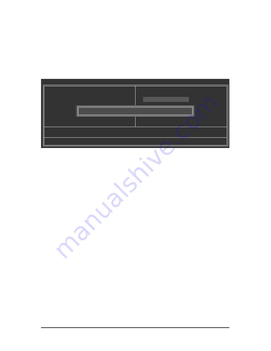
Press <Y> to load BIOS defaults

Step 4:
Press <Esc> and then <Enter> to exit Q-Flash and reboot the system. As the system boots, you should
see the new BIOS version is present on the POST screen.

Step 5:
During the POST, press <Delete> to enter BIOS Setup. Select 

Load Optimized Defaults 

and press

<Enter> to load BIOS defaults. System will re-detect all peripherals devices after a BIOS update, so we
recommend that you reload BIOS defaults.

CMOS Setup Utility-Copyright (C) 1984-2009 Award Software

MB Intelligent Tweaker(M.I.T.)

Standard CMOS Features

Advanced BIOS Features

Integrated Peripherals

Power Management Setup

PC Health Status

ESC: Quit



: Select Item

F11: Save CMOS to BIOS

F8: Q-Flash

F10: Save & Exit Setup

F12: Load CMOS from BIOS

Load Optimized Defaults

Load Fail-Safe Defaults
Load Optimized Defaults
Set Supervisor Password
Set User Password
Save & Exit Setup
Exit Without Saving

Load Optimized Defaults (Y/N)? Y

Summary of Contents for GA-MA770T-UD3

Page 1: ...GA MA770T UD3 GA MA770T US3 AM3 socket motherboard for AMD PhenomTM II X4 processor AMD PhenomTM II X3 processor User s Manual Rev 3101 12ME MA77TU3 3101R ...

Page 2: ...Motherboard GA MA770T UD3 GA MA770T US3 Jul 2 2010 Jul 2 2010 Motherboard GA MA770T UD3 GA MA770T US3 ...

Page 3: ...out GIGABYTE s prior written permission Documentation Classifications Inordertoassistintheuseofthisproduct GIGABYTEprovidesthefollowingtypesofdocumentations For quick set up of the product read the Quick Installation Guide included with the product Fordetailedproductinformation carefullyreadtheUser sManual For product related information check on our website at http www gigabyte com Identifying Yo...

Page 4: ... Channel Memory Configuration 16 1 4 2 Installing a Memory 17 1 5 Installing an Expansion Card 18 1 6 Back Panel Connectors 19 1 7 InternalConnectors 21 Chapter 2 BIOS Setup 33 2 1 StartupScreen 34 2 2 The Main Menu 35 2 3 MB Intelligent Tweaker M I T 37 2 4 Standard CMOS Features 42 2 5 Advanced BIOS Features 44 2 6 IntegratedPeripherals 46 2 7 Power Management Setup 50 2 8 PC Health Status 52 2 ...

Page 5: ...Easy Energy Saver 69 4 5 Q Share 71 4 6 TimeRepair 72 Chapter 5 Appendix 73 5 1 Configuring SATAHard Drive s 73 5 1 1 Configuring the Onboard SATA Controller 73 5 1 2 Making a SATA RAID AHCI Driver Diskette for Windows XP 79 5 1 3 Installing the SATA RAID AHCI Driver and Operating System 80 5 2 ConfiguringAudioInputandOutput 84 5 2 1 Configuring 2 4 5 1 7 1 Channel Audio 84 5 2 2 Configuring S PDI...

Page 6: ...art No 12CR1 1UB030 5 R 2 port IEEE 1394a bracket Part No 12CF1 1IE008 0 R 2 port SATA power cable Part No 12CF1 2SERPW 0 R COM port cable Part No 12CF1 1CM001 3 R S PDIF in cable Part No 12CR1 1SPDIN 0 R LPT port cable Part No 12CF1 1LP001 0 R The box contents above are for reference only and the actual items shall depend on product package you obtain The box contents are subject to change withou...

Page 7: ...R3_3 DDR3_4 BAT F_PANEL IT8720 SATA2_3 ATX_12V_2X4 AMD 770 AMD SB710 PWR_LED FDD PCIEX1_4 SATA2_2 PCI1 PCI2 CLR_CMOS LPT CODEC RTL8111D E PWR_FAN SYS_FAN1 F_USB1 SATA2_1 SATA2_0 SYS_FAN2 RCA_SPDIF R_USB SPDIF_OUT USB_1394_1 USB_1394_2 USB_LAN Socket AM3 AM3 CI PCIEX1_3 F_1394 TSB43AB23 B_BIOS SATA2_5 SATA2_4 COMA The GA MA770T UD3 adopts All Solid Capacitor design ...

Page 8: ...a 12 USB Ports LPT Port COM Port CPU CLK 200 MHz TSB43AB23 Center Subwoofer Speaker Out Line Out MIC Line In S PDIF In S PDIF Out Side Speaker Out Surround Speaker Out CODEC x 1 LAN RJ45 RTL8111D E ATA 133 100 66 33 IDE Channel PCIe CLK 100 MHz PCI Express x16 4 PCI Express x1 PCIe CLK 100 MHz x 1 x 1 x 1 x 1 PS 2 KB Mouse AMD SB710 Floppy IT8720 Dual BIOS 1 PCI Express x16 ...

Page 9: ...ands dry and first touch a metal object to eliminate static electricity Prior to installing the motherboard please have it on top of an antistatic pad or within an electrostaticshieldingcontainer Beforeunpluggingthepowersupplycablefromthemotherboard makesurethepowersupply hasbeenturnedoff Before turning on the power make sure the power supply voltage has been set according to the local voltage sta...

Page 10: ... Support for CD In LAN 1 x Realtek RTL8111D E chip 10 100 1000 Mbit Expansion Slots 1 x PCI Express x16 slot running at x16 The PCI Express x16 slot conforms to PCI Express 2 0 standard 4 x PCI Express x1 slots 2 x PCI slots Storage Interface South Bridge 1 x IDE connector supporting ATA 133 100 66 33 and up to 2 IDE devices 6 x SATA 3Gb s connectors supporting up to 6 SATA 3Gb s devices Support f...

Page 11: ...eader 1 x chassis intrusion header Back Panel 1 x PS 2 keyboard port Connectors 1 x PS 2 mouse port 1 x coaxial S PDIF Out connector 1 x optical S PDIF Out connector 8 x USB 2 0 1 1 ports 2 x IEEE 1394a ports 1 x RJ 45 port 6 x audio jacks Center Subwoofer Speaker Out Rear Speaker Out Side Speaker Out Line In Line Out Microphone I O Controller iTE IT8720 chip Hardware Monitor System voltage detect...

Page 12: ...orm Factor 30 5cm x 21 0cm Note 1 We recommend that you enhance heat dissipation for the CPU VRM area if an AMD Black Edition CPU is installed and Advanced Clock Calibration is enabled Note 2 Due to Windows Vista XP 32 bit operating system limitation when more than 4 GB of physical memory is installed the actual memory size displayed will be less than 4 GB Note 3 Use of a CPU that supports ECC is ...

Page 13: ...the computer if the CPU cooler is not installed otherwise overheating and damage of the CPU may occur Set the CPU host frequency in accordance with the CPU specifications It is not recom mended that the system bus frequency be set beyond hardware specifications since it does not meet the standard requirements for the peripherals If you wish to set the frequency beyond the standard specifications p...

Page 14: ... the CPU pins fit perfectly into their holes Once the CPU is positioned into its socket place one finger down on the middle of the CPU lowering the locking lever and latch ing it into the fully locked position Step 1 Completely lift up the CPU socket locking lever B Follow the steps below to correctly install the CPU into the motherboard CPU socket Before installing the CPU make sure to turn off t...

Page 15: ...layer of thermal grease on the surface of the installed CPU Step 2 Place the CPU cooler on the CPU Step 4 Turn the cam handle from the left side to the right side as the picture above shows to lock into place Refer to your CPU cooler installa tion manual for instructions on installing the cooler Step 3 Hook the CPU cooler clip to the mounting lug on one side of the retention frame On the other sid...

Page 16: ...g Dual Channel mode with two or four memory modules it is recommended that memory of the same capacity brand speed and chips be used and installed in the same colored DDR3 sockets for optimum performance Dual Channel Memory Configurations Table SS Single Sided DS Double Sided No Memory Two Modules Four Modules DDR3_1 DDR3_2 DDR3_3 DDR3_4 DS SS DS SS DS SS DS SS DS SS DS SS DS SS DS SS If two memor...

Page 17: ...orientation of the memory module Spread the retaining clips at both ends of the memory socket Place the memory module on the socket As indicated in the picture on the left place your fingers on the top edge of the memory push down on the memory and insert it vertically into the memory socket Step 2 The clips at both ends of the socket will snap into place when the memory module is securely inserte...

Page 18: ... fully seated in the slot 3 Make sure the metal contacts on the card are completely inserted into the slot 4 Secure the card s metal bracket to the chassis back panel with a screw 5 After installing all expansion cards replace the chassis cover s 6 Turn on your computer If necessary go to BIOS Setup to make any required BIOS changes for your expansion card s 7 Install the driver provided with the ...

Page 19: ...ovides digital audio out to an external audio system that supports digital coaxial audio Before using this feature ensure that your audio system provides a coaxial digital audio in connector USB Port The USB port supports the USB 2 0 1 1 specification Use this port for USB devices such as a USB keyboard mouse USB printer USB flash drive and etc IEEE 1394a Port The IEEE 1394 port supports the IEEE ...

Page 20: ...rs in a 5 1 7 1 channel audio configuration Rear Speaker Out Jack Black Use this audio jack to connect rear speakers in a 4 5 1 7 1 channel audio configuration Side Speaker Out Jack Gray Use this audio jack to connect side speakers in a 7 1 channel audio configuration Line In Jack Blue The default line in jack Use this audio jack for line in devices such as an optical drive walkman etc Line Out Ja...

Page 21: ... cord from the power outlet to prevent damage to the devices After installing the device and before turning on the computer make sure the device cable has been securely attached to the connector on the motherboard 1 2 3 4 5 17 6 7 8 9 12 14 15 4 11 16 13 1 ATX_12V_2X4 2 ATX 3 CPU_FAN 4 SYS_FAN1 SYS_FAN2 5 PWR_FAN 6 FDD 7 IDE 8 SATA2_0 1 2 3 4 5 9 PWR_LED 10 BAT 11 F_PANEL 12 F_AUDIO 13 CD_IN 14 SP...

Page 22: ...make sure the power supply is turned off and all devices are properly installed The power connector possesses a foolproof design Connect the power supply cable to the power connector in the correct orientation The 12V power connector mainly supplies power to the CPU If the 12V power connector is not connected the computer will not start To meet expansion requirements it is recommended that a power...

Page 23: ...ed Control 3 Sense 4 SpeedControl CPU_FAN Pin No Definition 1 GND 2 12V Speed Control 3 Sense 4 Reserve SYS_FAN1 Pin No Definition 1 GND 2 12V 3 Sense SYS_FAN2 PWR_FAN Be sure to connect fan cables to the fan headers to prevent your CPU and system from overheating Overheating may result in damage to the CPU or the system may hang These fan headers are not configuration jumper blocks Do not place a...

Page 24: ...nform to SATA 3Gb s standard and are compatible with SATA 1 5Gb s standard Each SATA connector supports a single SATA device The AMD SB710 controller supports RAID 0 RAID 1 RAID 10 and JBOD Refer to Chapter 5 Configuring SATA Hard Drive s for instructions on configuring a RAID array Pin No Definition 1 GND 2 TXP 3 TXN 4 GND 5 RXN 6 RXP 7 GND A RAID 0 or RAID 1 configuration requires at least two h...

Page 25: ...ff your computer and unplug the power cord before replacing the battery Replace the battery with an equivalent one Danger of explosion if the battery is replaced with an incorrect model Contact the place of purchase or local dealer if you are not able to replace the battery by yourself or uncertain about the battery model When installing the battery note the orientation of the positive side and th...

Page 26: ...rtup status by issuing a beep code One single short beep will be heard if no problem is detected at system startup If a problem is detected the BIOS may issue beeps in different patterns to indicate the problem Refer to Chapter 5 Troubleshooting for information about beep codes HD Hard Drive Activity LED Blue Connects to the hard drive activity LED on the chassis front panel The LED is on when the...

Page 27: ...rovides an AC 97 front panel audio module refer to the instructions on how to activate AC 97 functionality via the audio software in Chapter 5 Configuring 2 4 5 1 7 1 Channel Audio Audio signals will be present on both of the front and back panel audio connections simultaneously If you want to mute the back panel audio only supported when using an HD front panel audio module refer to Chapter 5 Con...

Page 28: ...cts a S PDIF digital audio cable provided by expansion cards for digital audio output from your motherboard to certain expansion cards like graphics cards and sound cards For example some graphics cards may require you to use a S PDIF digital audio cable for digital audio output from your motherboard to your graphics card if you wish to connect an HDMI display to the graphics card and have digital...

Page 29: ...IEEE 1394a bracket To connect an IEEE 1394a device attach one end of the device cable to your computer and then attach the other end of the cable to the IEEE 1394a device Ensure that the cable is securely connected 16 F_USB1 F_USB2 USB Headers The headers conform to USB 2 0 1 1 specification Each USB header can provide two USB ports via an optional USB bracket For purchasing the optional USB brack...

Page 30: ... PD1 6 INIT 7 PD2 8 SLIN 9 PD3 10 GND 11 PD4 12 GND 13 PD5 Pin No Definition 14 GND 15 PD6 16 GND 17 PD7 18 GND 19 ACK 20 GND 21 BUSY 22 GND 23 PE 24 No Pin 25 SLCT 26 GND 19 COMA Serial Port Header The COM header can provide one serial port via an optional COM port cable For purchasing the optional COM port cable please contact the local dealer Pin No Definition 1 NDCD 2 NSIN 3 NSOUT 4 NDTR 5 GND...

Page 31: ...ctory defaults To clear the CMOS values place a jumper cap on the two pins to temporarily short the two pins or use a metal object like a screwdriver to touch the two pins for a few seconds Always turn off your computer and unplug the power cord from the power outlet before clearing the CMOS values After clearing the CMOS values and before turning on your computer be sure to remove the jumper cap ...

Page 32: ...GA MA770T UD3 US3 Motherboard 32 ...

Page 33: ...y upgrade or back up BIOS without entering the operating system BIOS is a Windows based utility that searches and downloads the latest version of BIOS from the Internet and updates the BIOS For instructions on using the Q Flash and BIOS utilities refer to Chapter 4 BIOS Update Utilities Because BIOS flashing is potentially risky if you do not encounter problems using the current version of BIOS it...

Page 34: ...et the first boot device without entering BIOS Setup In Boot Menu use the up arrow key or the down arrow key to select the first boot device then press Enter to accept To exit Boot Menu press Esc The system will directly boot from the device configured in Boot Menu Note The setting in Boot Menu is effective for one time only After system restart the device boot order will still be based on BIOS Se...

Page 35: ...e selection bar to select an item Enter Execute command or enter the submenu Esc Main Menu Exit the BIOS Setup program Submenus Exit current submenu Page Up Increase the numeric value or make changes Page Down Decrease the numeric value or make changes F1 Show descriptions of the function keys F2 Move cursor to the Item Help block on the right submenus only F5 Restore the previous BIOS settings fo...

Page 36: ...y display adapter Integrated Peripherals Use this menu to configure all peripheral devices such as IDE SATA USB integrated audio and integrated LAN etc Power Management Setup Use this menu to configure all the power saving functions PC Health Status Use this menu to see information about autodetected system CPU temperature system voltage and fan speed etc Load Fail Safe Defaults Fail Safe defaults...

Page 37: ...ock Calibratioin Press Enter CPU Clock Ratio Auto 2800 Mhz CPU NorthBridge Freq Auto 2000 Mhz CPU Host Clock Control Auto x CPU Frequency MHz 200 PCIE Clock MHz Auto HT Link Frequency Auto Set Memory Clock Auto x Memory Clock x5 33 1066Mhz DRAM Configuration Press Enter System Voltage Optimized System Voltage Control Auto x CPU NB VID Control Auto x CPU Voltage Control Auto Normal CPU Vcore 1 2500...

Page 38: ... BIOS to automatically adjust the CPU host frequency Manual allows the CPU Frequency Mhz item below to be configurable Note If your system fails to boot after overclocking please wait for 20 seconds to allow for automated system reboot or clear the CMOS values to reset the board to default values CPU Frequency MHz Allows you to manually set the CPU host frequency The adjustable range is from 200 M...

Page 39: ...x Trfc1 for DIMM3 Auto x Trfc3 for DIMM4 Auto x Write Recovery Time Auto 8T 8T x Precharge Time Auto 3T 3T CMOS Setup Utility Copyright C 1984 2009 Award Software DRAM Configuration Move Enter Select PU PD Value F10 Save ESC Exit F1 General Help F5 Previous Values F6 Fail Safe Defaults F7 Optimized Defaults Item Help Menu Level x Row Cycle Time Auto 27T 27T x RAS to RAS Delay Auto 4T 4T CPU Host C...

Page 40: ... DIMM4 Options are 90ns 110ns 160ns 300ns 350ns Write Recovery Time Options are Auto default 5T 12T Precharge Time Options are Auto default 2T 3T Row Cycle Time Options are Auto default 11T 42T RAS to RAS Delay Options are Auto default 4T 7T System Voltage Optimized System Voltage Control Determines whether to manually set the system voltages Auto lets BIOS automatically set the system voltages as...

Page 41: ...voltage Normal Supplies the memory VTT voltage as required Default 0 900V 1 300V Adjusts the memory VTT voltage ranging from 0 900V to 1 300V NB Voltage Control Allows you to set the North Bridge voltage Normal Supplies the North Bridge voltage as required Default 1 100V 1 800V Adjusts the North Bridge voltage ranging from 1 100V to 1 800V SB HT Voltage Control Allows you to set the South Bridge H...

Page 42: ...nel 2 3 Master Slave IDE Auto Detection Press Enter to autodetect the parameters of the IDE SATA device on this channel Extended IDE Drive Configure your IDE SATA devices by using one of the two methods below Auto Lets BIOS automatically detect IDE SATA devices during the POST Default None If no IDE SATA devices are used set this item to None so the system will skip the detection of the device dur...

Page 43: ...oppy disk drive a Japanese standard floppy disk drive Options are Disabled default Drive A Halt On Allows you to determine whether the system will stop for an error during the POST No Errors The system boot will not stop for any error All Errors Whenever the BIOS detects a non fatal error the system boot will stop All But Keyboard The system boot will not stop for a keyboard error but stop for all...

Page 44: ...y to select a device and press Enter to accept Options are Floppy LS120 Hard Disk CDROM ZIP USB FDD USB ZIP USB CDROM USB HDD Legacy LAN Disabled Password Check Specifies whether a password is required every time the system boots or only when you enter BIOS Setup After configuring this item set the password s under the Set Supervisor User Password item in the BIOS Main Menu Setup A password is onl...

Page 45: ...tasks while in a low power mode that appears off Default Disabled Full Screen LOGO Show Allows you to determine whether to display the GIGABYTE Logo at system startup Disabled displays normal POST message Default Enabled Backup BIOS Image to HDD Allows the system to copy the BIOS image file to the hard drive If the system BIOS is corrupted it will be recovered from this image file Default Enabled ...

Page 46: ...t Disabled CMOS Setup Utility Copyright C 1984 2009 Award Software Integrated Peripherals OnChip IDE Channel Enabled Onboard 1394 Function Enabled Onboard LAN Function Enabled Onboard LAN Boot ROM Disabled SMART LAN Press Enter OnChip SATA Controller Enabled OnChip SATA Type Native IDE x OnChip SATA Port4 5 Type IDE Onboard Audio Function Enabled OnChip USB Controller Enabled USB EHCI Controller E...

Page 47: ... show 0m as shown in the figure above Link Detected Displays transmission speed Cable Length Displays the approximate length of the attached LAN cable Start detecting at Port Link Detected 100Mbps Cable Length 30m Note The Gigabit hub will only operate at a speed of 10 100Mbps in MS DOS mode it will operate at a normal speed of 10 100 1000 Mbps in Windows mode or when the LAN Boot ROM is activated...

Page 48: ...to PATA mode Default As SATA Type The mode depends on the OnChip SATA Type settings Onboard Audio Function Enables or disables the onboard audio function Default Auto If you wish to install a 3rd party add in audio card instead of using the onboard audio set this item to Disabled OnChip USB Controller Enables or disables the integrated USB 1 1 controller Default Enabled USB EHCI Controller Enables...

Page 49: ...port Options are SPP Standard Parallel Port default EPP Enhanced Parallel Port ECP Extended Capabilities Port ECP EPP ECP Mode Use DMA Selects DMA channel for the LPT port in ECP mode This item is configurable only if Parallel Port Mode is set to ECP or ECP EPP mode Options are 3 default 1 ...

Page 50: ...to turn off the system If the power button is pressed for less than 4 seconds the system will enter suspend mode USB Wake Up from S3 Allows the system to be awakened from ACPI S3 sleep state by a wake up signal from the installed USB device Default Enabled Modem Ring Resume Allows the system to be awakened from an ACPI sleep state by a wake up signal from a modem that supports wake up function Def...

Page 51: ... with up to 5 characters and then press Enter to accept To turn on the system enter the password and press Enter Note To cancel the password press Enter on this item When prompted for the password press Enter again without entering the password to clear the password settings AC Back Function Determines the state of the system after the return of power from an AC power loss Soft Off The system stay...

Page 52: ... Case Open Status Disabled Case Opened No Vcore 1 376V DDR3 1 5V 1 536V 3 3V 3 328V 12V 12 112V Current System Temperature 30o C Current CPU Temperature 47o C Current CPU FAN Speed 3375 RPM Current SYSTEM FAN1 Speed 0 RPM Current SYSTEM FAN2 Speed 0 RPM Current POWER FAN Speed 0 RPM CPU Warning Temperature Disabled CPU FAN Fail Warning Disabled SYSTEM FAN1 Fail Warning Disabled SYSTEM FAN2 Fail Wa...

Page 53: ...Default Disabled CPU Smart FAN Control Enables or disables the CPU fan speed control function Enabled allows the CPU fan to run at different speed according to the CPU temperature You can adjust the fan speed with EasyTune based on system requirements If disabled CPU fan runs at full speed Default Enabled CPU Smart FAN Mode Specifies how to control CPU fan speed This item is configurable only if C...

Page 54: ... I T Standard CMOS Features Advanced BIOS Features Integrated Peripherals Power Management Setup PC Health Status ESC Quit Select Item F11 Save CMOS to BIOS F8 Q Flash F10 Save Exit Setup F12 Load CMOS from BIOS Load Fail Safe Defaults Load Fail Safe Defaults Load Optimized Defaults Set Supervisor Password Set User Password Save Exit Setup Exit Without Saving Load Fail Safe Defaults Y N N CMOS Set...

Page 55: ...ter the supervisor password or user password at system startup to continue system boot In BIOS Setup you must enter the supervisor password if you wish to make changes to BIOS settings The user password only allows you to view the BIOS settings but not to make changes To clear the password press Enter on the password item and when requested for the password press Enter again The message PASSWORD D...

Page 56: ...erals Power Management Setup PC Health Status ESC Quit Select Item F11 Save CMOS to BIOS F8 Q Flash F10 Save Exit Setup F12 Load CMOS from BIOS Save Data to CMOS Load Fail Safe Defaults Load Optimized Defaults Set Supervisor Password Set User Password Save Exit Setup Exit Without Saving Save to CMOS and EXIT Y N Y CMOS Setup Utility Copyright C 1984 2009 Award Software MB Intelligent Tweaker M I T...

Page 57: ...to manually select the drivers you wish to install Please ignore the popup dialog box es e g the Found New Hardware Wizard displayed when Xpress Install is installing the drivers Failure to do so may affect the driver installation Some device drivers will restart your system automatically during the driver installation After the system restart Xpress Install will continue to install other drivers ...

Page 58: ... utilities and applications that GIGABYTE develops and some free software You can click the Install button on the right of an item to install it 3 3 Technical Manuals This page provides GIGABYTE s application guides content descriptions for this driver disk and the motherboard manuals ...

Page 59: ...4 Contact For the detailed contact information of the GIGABYTE Taiwan headquarter or worldwide branch offices click the URL on this page to link to the GIGABYTE Website 3 5 System This page provides the basic system information ...

Page 60: ...3 Motherboard 60 3 6 Download Center To update the BIOS drivers or applications click the Download Center button to link to the GIGABYTE Web site The latest version of the BIOS drivers or applications will be displayed ...

Page 61: ...nly back up restore the first physical hard drive that has the operating system installed As Xpress Recovery2 will save the backup file at the end of the hard drive make sure to leave enough unallocated space in advanced 10 GB or more is recommended actual size require ments vary depending on the amount of data It is recommended to back up your system soon after the operating system and drivers ar...

Page 62: ...ted space Xpress Recovery2 cannot save the backup file B Accessing Xpress Recovery2 1 Boot from the motherboard driver disk to access Xpress Recovery2 for the first time When you see the following message Press any key to startup Xpress Recovery2 press any key to enter Xpress Recovery2 2 After you use the backup function in Xpress Recovery2 for the first time Xpress Recovery2 will stay permanent i...

Page 63: ...ry2 Select RESTORE to restore the backup to your hard drive in case the system breaks down The RESTORE option will not be present if no backup is created before Step 1 If you wish to remove the backup file select REMOVE Step 2 After the backup file is removed no backup image file will be present in Disk Management and hard drive space will be freed up ...

Page 64: ...he BIOS without the need to enter MS DOS mode Additionally this motherboard features the DualBIOSTM design which enhances protection for the safety and stability of your computer by adding one more physical BIOS chip What is DualBIOSTM Motherboards that support DualBIOS have two BIOS onboard a main BIOS and a backup BIOS Normally the system works on the main BIOS However if the main BIOS is corrup...

Page 65: ...B 1M Keep DMI Data Enable Update BIOS from Drive Save BIOS to Drive Enter Run Move ESC Reset F10 Power Off 0 file s found Floppy A Drive HDD 0 0 Drive Total size 0 Free size 0 3 Select the BIOS update file and press Enter Make sure the BIOS update file matches your motherboard model Step 2 The process of the system reading the BIOS file from the floppy disk is displayed on the screen When the mess...

Page 66: ...mized Defaults and press Enter to load BIOS defaults System will re detect all peripherals devices after a BIOS update so we recommend that you reload BIOS defaults CMOS Setup Utility Copyright C 1984 2009 Award Software MB Intelligent Tweaker M I T Standard CMOS Features Advanced BIOS Features Integrated Peripherals Power Management Setup PC Health Status ESC Quit Select Item F11 Save CMOS to BIO...

Page 67: ...n Update the BIOS without Using the Internet Update Function below 2 Update the BIOS without Using the Internet Update Function Click Update BIOS from File then select the location where you save the BIOS update file obtained from the Internet or through other source Follow the on screen instructions to complete 1 Update the BIOS Using the Internet Update Function Click Update BIOS from GIGABYTE S...

Page 68: ...installed CPU and motherboard The Memory tab provides information on the installed memory module s You can select memory module on a specific slot to see its information The Tuner tab allows you to change system clock settings and voltages Easy Mode allows you to adjust the CPU FSB only Advanced Mode allows you to individually change system clock settings and voltages settings using the sliders Ea...

Page 69: ...ve data is for reference only Actual performance may vary depending on motherboard model CPU Power and Power Scores are for reference only Actual results may vary based on testing method Button Description 1 Easy Energy Saver On Off Switch Default Off 2 Dynamic CPU Frequency Function On Off Switch Default Off Note 1 3 CPU Throttling Display 4 CPU Voltage Display 5 3 Level CPU Voltage Switch Defaul...

Page 70: ...lly reset when the total power saving reaches 99999999 Watts Button Description 1 Easy Energy Saver On Off Switch Default Off 2 Dynamic CPU Frequency Function On Off Switch Default Off 3 CPU Throttling Display 4 CPU Voltage Display 5 3 Level CPU Voltage Switch Default 1 Note 2 6 Current CPU Power Consumption 7 Time Date Easy Energy Saver Enabled 8 Total Power Savings Total power saving with Easy E...

Page 71: ...tray and right click on this icon to configure the data sharing settings Figure 2 Data Sharing Enabled Figure 1 Data Sharing Disabled Options Descriptions Note This option is available only when data sharing is NOT enabled Option Description Connect Displays the computers with data sharing enabled Enable Incoming Folder Enables data sharing Disable Incoming Folder Disables data sharing Open Incomi...

Page 72: ...s directory ies or click Restore to restore the entire system Button Function ON Automatically creates system restore points OFF DO NOT automatically create system restore points SCHEDULE Sets a regular interval for creating system restore points CAPACITY Sets the percentage of hard drive space used for saving shadow copies TRIGGER Creates a system restore point upon the first boot up of the day D...

Page 73: ...E Install the SATA RAID AHCI driver and operating system Note 2 Before you begin Please prepare At least two SATA hard drives to ensure optimal performance it is recommended that you use two hard drives with identical model and capacity If you do not want to create RAID you may prepare only one hard drive An empty formatted floppy disk Windows Vista XP setup disk Motherboard driver disk 5 1 1 Conf...

Page 74: ...nu options you will see shall depend on the motherboard you have and the BIOS version Step 2 Save changes and exit BIOS Setup Figure 1 CMOS Setup Utility Copyright C 1984 2009 Award Software Integrated Peripherals OnChip IDE Channel Enabled Onboard 1394 Function Enabled Onboard LAN Function Enabled Onboard LAN Boot ROM Disabled SMART LAN Press Enter OnChip SATA Controller Enabled OnChip SATA Type ...

Page 75: ...ights reserved No Array is defined Press Ctrl F to enter FastBuild tm Utility Step 2 Main Menu This is the first option screen when you enter the BIOS RAID Setup utility Figure 3 To view the disk drives assigned to arrays press 1 to enter the View Drive Assignments window To create an array press 2 to enter the Define LD window To delete an array press 3 to enter the Delete LD window To view contr...

Page 76: ...ode Total Drv Capacity GB Status LD 1 LD 2 LD 3 LD 4 LD 5 LD 6 LD 7 LD 8 LD 9 LD 10 Figure 4 In Figure 4 use the up or down arrow key to move to a logical disk set and press Enter to enter the RAID configuration menu Figure 5 Figure 5 Up Down ESC Exit Space Change Ctrl Y Save PgUp Dn Page Change Option ROM Utility c 2008 Advanced Micro Devices Inc Keys Available Define LD Menu LD No RAID Mode Tota...

Page 77: ...8 6 Press Ctrl Y to clear the MBR or press other keys to ignore this option Then the window below will appear Fast Initialization option has been selected It will erase the MBR data of the disk Press Ctrl Y key if you are sure to erase it Press any other key to ignore this option Figure 6 7 Press Ctrl Y to set the capacity of the RAID array or press other keys to set the array to its maximum capac...

Page 78: ...leted the screen will return to Delete LD Menu Press Esc to return to Main Menu Deleting an existing disk array could result in loss of data Record all array information including the array type the disk members and stripe block size in case you wish to undo a deletion Figure 9 Option ROM Utility c 2008 Advanced Micro Devices Inc View LD Definition Menu LD No RAID Mode Total Drv Capacity GB Status...

Page 79: ...ed to install the SATA controller driver during the OS installation Without the driver the hard drive may not be recognized during the Windows setup process First of all copy the driver for the SATA controller from the motherboard driver disk to a floppy disk For installing Windows Vista you also can copy the SATA controller driver from the motherboard driver disk to a USB flash drive See the inst...

Page 80: ...rd drive s The followings are examples of Windows XP and Vista installation A Installing Windows XP Step 1 Restart your system to boot from the Windows XP setup disk and press F6 as soon as you see the message Press F6 if you need to install a 3rd party SCSI or RAID driver Figure 1 A screen will then appear asking you to specify additional device Insert the floppy disk containing the SATA RAID AHC...

Page 81: ... Method B then specify the location of the driver Figure 4 Note For users using a SATA optical drive be sure to copy the driver files from the motherboard driver disk to a USB flash drive before installing Windows Vista go to the BootDrv folder and save the whole SB750V folder to the USB flash drive Then use Method B to load the driver Method A Insert the motherboard driver disk into your system a...

Page 82: ...ompatible RAID Controller and press Next Figure 5 Step 4 After the driver is loaded the RAID drive will appear Select the RAID drive and then press Next to continue the OS installation Figure 6 Figure 6 The install menus described in this chapter are for reference only and may differ by driver version ...

Page 83: ...en installed from the motherboard driver disk Then launch the AMD RAIDXpert from All Programs in the Start Menu Step 1 Enter the login ID and password default admin and then click Sign in to launch AMD RAIDXpert Step 2 Select the RAID array to be rebuilt under Logical Drive View and click the Rebuild tab in the Logical Drive Information pane Step 3 Select one available drive and click Start Now to...

Page 84: ... chat make a telephone call over the Internet and etc all at the same time A Configuring Speakers The following instructions use Windows Vista as the example operating system To install a microphone connect your microphone to the Mic in jack and manually configure the jack for microphone functionality Audio signals will be present on both of the front and back panel audio connections simultaneousl...

Page 85: ... Effect You may configure an audio environment on the Sound Effects tab If your chassis provides an AC 97 front panel audio module to activate the AC 97 functionality click the tool icon on the Speaker Configuration tab On the Connector Settings dialog box select the Disable front panel jack detection check box Click OK to complete D Muting the Back Panel Audio For HD Audio Only C Activating an AC...

Page 86: ...t tab to select the default format Click OK to complete Step 1 First attach the connector at the end of the cable to the SPDIF_IN header on your motherboard Step 2 Secure the metal bracket to the chassis back panel with a screw Coaxial S PDIF In Optical S PDIF In S PDIF In Cable 5 2 2 Configuring S PDIF In Out A S PDIF In The S PDIF In cable optional allows you to input digital audio signals to th...

Page 87: ...ital audio signals S PDIF Coaxial Cable S PDIF Optical Cable 2 Configuring S PDIF Out On the Digital Output Optical screen Note click the Default Format tab and then select the sample rate and bit depth Click OK to complete Note Enter the Digital Output Optical screen to configure further settings if you use the S PDIF Out connector s on the back panel for digital audio output or enter the Digital...

Page 88: ...Go to the Microphone screen Do not mute the recording volume or you ll not be able to record the sound To hear the sound being recorded during the recording process do not mute the playback volume It is recommended that you set the volumes at a middle level Step 1 After installing the audio driver the HD Audio Manager icon will appear in the notification area Double click the icon to access the HD...

Page 89: ...Manager does not display the recording device you wish to use refer to the steps below The following steps explain how to enable Stereo Mix which may be needed when you want to record sound from your computer Step 1 Locate the Volume icon in the notification area and right click on this icon Select Recording Devices Step 4 To raise the recording and playback volume for the microphone click the Mic...

Page 90: ...he default device A Recording Sound 1 Make sure you have connected the sound input device e g microphone to the computer 2 To record the audio click the Start Recording button 3 To stop recording audio click the Stop Recording button Be sure to save the recorded audio file upon completion B Playing the Recorded Sound You can play your recording in a digital media player program that supports your ...

Page 91: ...all the onboard HD audio driver successfully For Windows XP only A Step 1 First make sure Service Pack 1 or Service Pack 2 has been installed check in My Computer Properties General System If not please update it from Microsoft s website Then make sure the Microsoft UAA Bus Driver for High Definition Audio has been installed successfully check in My Computer Properties Hardware Device Manager Syst...

Page 92: ...erly Check if the memory is installed properly on the memory slot Yes Yes START Make sure the motherboard does not short circuit with the chassis or other metal objects Insertthegraphicscard ConnecttheATXmainpowercableandthe12V power cable Turn on the power to start the computer No Secure the CPU cooler on the CPU Connect the CPU cooler power cable to the motherboard No Correctly insert the memory...

Page 93: ... or keyboard connec tor might fail A Turn off the computer and connect the IDE SATA devices Check if the system can boot successfully Press Delete to enter BIOS Setup Select Load Fail Safe Defaults or Load Optimized Defaults Select Save Exit Setup to save changes and exit BIOS Setup The problem is verified and solved The problem is verified and solved The problem is verified and solved The problem...

Page 94: ...GA MA770T UD3 US3 Motherboard 94 ...

Page 95: ...Appendix 95 ...

Page 96: ...GA MA770T UD3 US3 Motherboard 96 ...

Page 97: ...Appendix 97 ...

Page 98: ...GA MA770T UD3 US3 Motherboard 98 ...

Page 99: ... us Web address http latam giga byte com GIGA BYTE SINGAPORE PTE LTD Singapore WEB address http www gigabyte sg Thailand WEB address http th giga byte com Vietnam WEB address http www gigabyte vn NINGBO G B T TECH TRADING CO LTD China WEB address http www gigabyte cn Shanghai TEL 86 21 63410999 FAX 86 21 63410100 Beijing TEL 86 10 62102838 FAX 86 10 62102848 Wuhan TEL 86 27 87851061 FAX 86 27 8785...

Page 100: ...gigabyte fr Sweden WEB address http www gigabyte se Italy WEB address http www giga byte it Spain WEB address http www giga byte es Greece WEB address http www gigabyte com gr Czech Republic WEB address http www gigabyte cz Hungary WEB address http www giga byte hu Turkey WEB address http www gigabyte com tr Russia WEB address http www gigabyte ru Poland WEB address http www gigabyte pl Ukraine WE...

Reviews: