background image

Hardware Installation

- 12 -

1-3  Installing the CPU and CPU Cooler

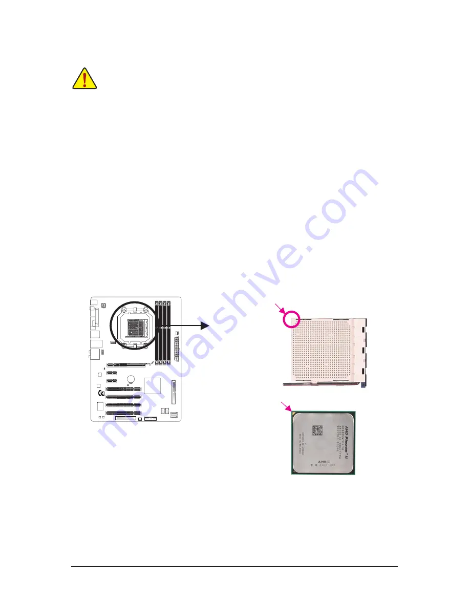
1-3-1  Installing the CPU

A.  Locate the pin one (denoted by a small triangle) of the CPU socket and the CPU.

Read the following guidelines before you begin to install the CPU:  

• 

Make sure that the motherboard supports the CPU.

  (Go to GIGABYTE's website for the latest CPU support list.)

• 

Always turn off the computer and unplug the power cord from the power outlet before installing 
the CPU to prevent hardware damage.

• 

Locate the pin one of the CPU. The CPU cannot be inserted if oriented incorrectly. (Or you may 
locate the notches on both sides of the CPU and alignment keys on the CPU socket.)

• 

Apply an even and thin layer of thermal grease on the surface of the CPU.

• 

Do not turn on the computer if the CPU cooler is not installed, otherwise overheating and dam-
age of the CPU may occur.

• 

Set the CPU host frequency in accordance with the CPU specifications. It is not recommended 
that the system bus frequency be set beyond hardware specifications since it does not meet the 

standard requirements for the peripherals. If you wish to set the frequency beyond the standard 

specifications, please do so according to your hardware specifications including the CPU, graph

-

ics card, memory, hard drive, etc.

AM3 CPU

AM3 Socket

A Small Triangle Marking 
Denotes CPU Pin One

A Small Triangle Mark 
Denotes Pin One of the 
Socket 

Summary of Contents for GA-M52L-S3P

Page 1: ...GA M52LT D3 GA M52LT S3P AM3 socket motherboard for AMD Phenom II processor AMD Athlon II processor User s Manual Rev 2301 12ME M52LTD3 2301R...

Page 2: ...Motherboard May 28 2010 May 28 2010 Motherboard GA M52LT D3 GA M52LT S3P GA M52LT D3 GA M52LT S3P...

Page 3: ...euseofthisproduct GIGABYTEprovidesthefollowingtypesofdocumentations For quick set up of the product read the Quick Installation Guide included with the product For detailed product information careful...

Page 4: ...ual Channel Memory Configuration 15 1 4 2 Installing a Memory 16 1 5 Installing an Expansion Card 17 1 6 Back Panel Connectors 18 1 7 Internal Connectors 20 Chapter 2 BIOS Setup 29 2 1 Startup Screen...

Page 5: ...61 4 3 EasyTune 6 62 4 4 Auto Green 63 Chapter 5 Appendix 65 5 1 Configuring SATA Hard Drive s 65 5 1 1 Configuring the Onboard SATA Controller 65 5 1 2 Making a SATA RAID Driver Diskette 70 5 1 3 In...

Page 6: ...ive cable Part No 12CF1 1FD001 7 R 2 port USB 2 0 bracket Part No 12CR1 1UB030 5 R 2 port SATA power cable Part No 12CF1 2SERPW 0 R S PDIF In cable Part No 12CR1 1SPDIN 0 R The box contents above are...

Page 7: ...1 IDE DDR3_1 DDR3_3 DDR3_2 DDR3_4 F_PANEL SYS_FAN iTE IT8720 ATX_12V NVIDIA nForce 520LE PCI3 PCI4 USB_LAN CODEC PWR_FAN PCIEX1_2 Realtek RTL8201EL COAXIAL COMA R_USB PCIEX16 SPDIF_I SPDIF_O F_USB1 FD...

Page 8: ...66 33 IDE Channel 8 USB 2 0 1 1 LPC Bus Dual Channel Memory Center Subwoofer Speaker Out Line Out MIC Line In S PDIF In S PDIF Out Side Speaker Out Surround Speaker Out CODEC 2 SATA 3Gb s PCIe CLK 10...

Page 9: ...and first touch a metal object to eliminate static electricity Prior to installing the motherboard please have it on top of an antistatic pad or within an electrostatic shielding container Before unp...

Page 10: ...x16 slot running at x16 2 x PCI Express x1 slots 4 x PCI slots Storage Interface Chipset 1 x IDE connector supporting ATA 133 100 66 33 and up to 2 IDE devices 2 x SATA 3Gb s connectors supporting up...

Page 11: ...ofer Speaker Out Rear Speaker Out Side Speaker Out Line In Line Out Microphone I O Controller w iTE IT8720 chip Hardware Monitor w System voltage detection w CPU System temperature detection w CPU Sys...

Page 12: ...s on both sides of the CPU and alignment keys on the CPU socket Apply an even and thin layer of thermal grease on the surface of the CPU Do not turn on the computer if the CPU cooler is not installed...

Page 13: ...ure that the CPU pins fit perfectly into their holes Once the CPU is positioned into its socket place one finger down on the middle of the CPU lowering the locking lever and latching it into the fully...

Page 14: ...ayer of thermal grease on the surface of the installed CPU Step 2 Place the CPU cooler on the CPU Step 3 Hook the CPU cooler clip to the mounting lug on one side of the retention frame On the other si...

Page 15: ...rom the power outlet before installing the memory to prevent hardware damage Memory modules have a foolproof design A memory module can be installed in only one direc tion If you are unable to insert...

Page 16: ...on the left place your fin gers on the top edge of the memory push down on the memory and insert it vertically into the memory socket Step 2 The clips at both ends of the socket will snap into place w...

Page 17: ...th the slot and press down on the card until it is fully seated in the slot 3 Make sure the metal contacts on the card are completely inserted into the slot 4 Secure the card s metal bracket to the ch...

Page 18: ...s data rate The following de scribes the states of the LAN port LEDs When removing the cable connected to a back panel connector first remove the cable from your device and then remove it from the mot...

Page 19: ...Mic In Jack Pink The default Mic in jack Microphones must be connected to this jack In addition to the default speakers settings the audio jacks can be reconfigured to per form different functions via...

Page 20: ...evices and your computer Unplug the power cord from the power outlet to prevent damage to the devices After installing the device and before turning on the computer make sure the device cable has been...

Page 21: ...rboard Before connecting the power connector first make sure the power supply is turned off and all devices are properly installed The power connector possesses a foolproof design Connect the power su...

Page 22: ...U_FAN 1 Be sure to connect fan cables to the fan headers to prevent your CPU and system from over heating Overheating may result in damage to the CPU or the system may hang These fan headers are not c...

Page 23: ...the instructions from the device manufacturers 2 40 1 39 8 SATA2_0 1 SATA 3Gb s Connectors The SATA connectors conform to SATA 3Gb s standard and are compatible with SATA 1 5Gb s standard Each SATA c...

Page 24: ...writing data RES Reset Switch Green Connects to the reset switch on the chassis front panel Press the reset switch to restart the computer if the computer freezes and fails to perform a normal restar...

Page 25: ...nt panel audio header supports HD audio by default If your chassis provides an AC 97 front panel audio module refer to the instructions on how to activate AC 97 functionality via the audio software in...

Page 26: ...ital S PDIF Out and connects a S PDIF digital audio cable provided by expan sion cards for digital audio output from your motherboard to certain expansion cards like graphics cards and sound cards For...

Page 27: ...Use this jumper to clear the CMOS values e g date information and BIOS configurations and reset the CMOS values to factory defaults To clear the CMOS values place a jumper cap on the two pins to temp...

Page 28: ...touch the positive and negative terminals of the battery holder making them short for 5 seconds 3 Replace the battery 4 Plug in the power cord and restart your computer Always turn off your computer a...

Page 29: ...BIOS without entering the operating system BIOS is a Windows based utility that searches and downloads the latest version of BIOS from the Internet and updates the BIOS For instructions on using the Q...

Page 30: ...the up arrow key h or the down arrow key i to select the first boot device then press Enter to accept To exit Boot Menu press Esc The system will directly boot from the device configured in Boot Menu...

Page 31: ...F2 Move cursor to the Item Help block on the right submenus only F5 Restore the previous BIOS settings for the current submenus F6 Load the Fail Safe BIOS default settings for the current submenus F7...

Page 32: ...odetected system CPU temperature system voltage and fan speed etc Load Fail Safe Defaults Fail Safe defaults are factory settings for the most stable minimal performance system operations Load Optimiz...

Page 33: ...quency The adjustable range is from 100 MHz to 145 MHz Default 100 CPU Clock Ratio Allows you to alter the clock ratio for the installed CPU The adjustable range is dependent on the CPU being used CPU...

Page 34: ...10T x Precharge Time Auto 5T 5T x Row Cycle Time Auto 33T 33T x RAS to RAS Delay Auto 4T 4T CKE Power Down Mode Disabled CKE Power Down Control per Channel DCTs Mode Note Allows you to set memory cont...

Page 35: ...wer down mode Options are per Channel Default per CS DDR3 Voltage Control Allows you to set memory voltage Normal Supplies the memory voltage as required Default 0 1V 0 7V The adjustable range is from...

Page 36: ...CHS LBA Large IDE Channel 2 3 Master IDE Auto Detection Press Enter to autodetect the parameters of the IDE SATA device on this channel Extended IDE Drive Configure your IDE SATA devices by using one...

Page 37: ...ppy disk drive a Japanese standard floppy disk drive Options are Disabled default Drive A Halt On Allows you to determine whether the system will stop for an error during the POST All Errors Whenever...

Page 38: ...the two items below to be configurable Auto Lets the BIOS to enable all CPU cores number of cores available depends on the CPU being used Default Manual Allows you to individually enable disable CPU...

Page 39: ...tering the BIOS Setup program HDD S M A R T Capability Enables or disables the S M A R T Self Monitoring and Reporting Technology capability of your hard drive This feature allows your system to repor...

Page 40: ...ables or disables RAID for the integrated SATA 3Gb s controller Enabled allows you to configure RAID for individual SATA channel Default Disabled NV SATA 1 Primary RAID Enables or disables RAID for th...

Page 41: ...address and corresponding interrupt Options are Auto 2F8 IRQ3 3F8 IRQ4 default 3E8 IRQ4 2E8 IRQ3 Disabled Onboard Parallel Port Enables or disables the onboard parallel port LPT and specifies its base...

Page 42: ...n ACPI sleep state by a wake up signal from a PCI or PCIe de vice Note To use this function you need an ATX power supply providing at least 1A on the 5VSB lead Default Enabled Modem Ring On Allows the...

Page 43: ...ck Double click on left button on the PS 2 mouse to turn on the system Power On By Keyboard Allows the system to be turned on by a PS 2 keyboard wake up event Note you need an ATX power supply providi...

Page 44: ...fault 3 4 5 7 9 10 11 12 14 15 Assigns IRQ 3 4 5 7 9 10 11 12 14 15 to the third PCI slot PCI 4 IRQ Assignment Auto BIOS auto assigns IRQ to the fourth PCI slot Default 3 4 5 7 9 10 11 12 14 15 Assign...

Page 45: ...F 70o C 158o F 80o C 176o F 90o C 194o F CPU SYSTEM FAN Fail Warning Allows the system to emit warning sound if the CPU system fan is not connected or fails Check the fan condition or fan connection w...

Page 46: ...of CPU fan installed and sets the optimal CPU fan control mode Default Voltage Sets Voltage mode for a 3 pin CPU fan PWM Sets PWM mode for a 4 pin CPU fan System Smart FAN Control Enables or disables...

Page 47: ...sor Password Set User Password Save Exit Setup Exit Without Saving Load Fail Safe Defaults Y N N Press Enter on this item and then press the Y key to load the optimal BIOS default settings The BIOS de...

Page 48: ...ord or user password at system startup to continue system boot In BIOS Setup you must enter the supervisor password if you wish to make changes to BIOS settings The user password only allows you to vi...

Page 49: ...BIOS Features Integrated Peripherals Power Management Setup PnP PCI Configurations PC Health Status ESC Quit Select Item F8 Q Flash F10 Save Exit Setup Load Fail Safe Defaults Load Optimized Defaults...

Page 50: ...BIOS Setup 50...

Page 51: ...o manually select the drivers you wish to install Please ignore the popup dialog box es e g the Found New Hardware Wizard displayed when Xpress Install is installing the drivers Failure to do so may a...

Page 52: ...ties and applications that GIGABYTE develops and some free software You can click the Install button on the right of an item to install it 3 3 Technical Manuals This page provides GIGABYTE s applicati...

Page 53: ...4 Contact For the detailed contact information of the GIGABYTE Taiwan headquarter or worldwide branch offices click the URL on this page to link to the GIGABYTE website 3 5 System This page provides t...

Page 54: ...d Center button to link to the GIGABYTE website The latest version of the BIOS drivers or applications will be displayed 3 7 New Utilities This page provides a quick link to GIGABYTE s lately develope...

Page 55: ...cked up restored It takes longer to back up a hard drive than to restore it System Requirements At least 512 MB of system memory VESA compatible graphics card Windows XP with SP1 or later Windows Vist...

Page 56: ...ll save the backup file to the unallocated space black stripe along the top Please note that if there is no enough unallocated space Xpress Recovery2 cannot save the backup file B Accessing Xpress Rec...

Page 57: ...p to your hard drive in case the system breaks down The RESTORE option will not be present if no backup is created before Select REBOOT to exit Xpress Recovery2 Step 2 After the backup file is removed...

Page 58: ...cess What is BIOS BIOS allows you to update the system BIOS while in the Windows environ ment BIOS will download the latest BIOS file from the nearest BIOS server site and update the BIOS 4 2 1 Updati...

Page 59: ...the current BIOS file Q Flash only supports USB flash drive or hard drives using FAT32 16 12 file system If the BIOS update file is saved to a hard drive in RAID AHCI mode or a hard drive attached to...

Page 60: ...Select Save Exit Setup and then press Y to save settings to CMOS and exit BIOS Setup The proce dure is complete after the system restarts Press Y to load BIOS defaults CMOS Setup Utility Copyright C...

Page 61: ...atches your motherboard model Follow the on screen instructions to complete 2 Update the BIOS without Using the Internet Update Function Click Update BIOS from File then select the location where you...

Page 62: ...ormation The Tuner tab allows you to change system clock settings and voltages Easy mode allows you to adjust the CPU FSB only Advanced mode allows you to individually change system clock settings and...

Page 63: ...etermined period of time After completing the settings click Set for the settings to take effect and then click Exit to quit Configuring the Bluetooth cell phone key After you select a cell phone the...

Page 64: ...Unique Features 64...

Page 65: ...ensure optimal performance it is recommended that you use two hard drives with identical model and capacity If you do not want to create RAID you may prepare only one hard drive An empty formatted fl...

Page 66: ...ary RAID to Enabled Figure 2 CMOS Setup Utility Copyright C 1984 2010 Award Software Serial ATA RAID Config NV SATA RAID function Enabled NV SATA 1 Primary RAID Enabled NV SATA 1 Secondary RAID Enable...

Page 67: ...AID mode The supported RAID modes in clude Mirroring Striping Stripe Mirroring RAID 5 and Spanning The following procedure demonstrates how a RAID 0 array Striping is created Step 4 If RAID 0 Striping...

Page 68: ...e target hard drives using the up or down arrow key and use the right arrow key to add the hard drives to the Array Disks block Figure 5 MediaShield Utility Nov 20 2006 Define a New Array ESC Quit F6...

Page 69: ...hard drive model name and hard drive capacity etc To delete the array press D in the Array Detail screen When the Delete this array message appears press Y to confirm or N to cancel Press Enter to re...

Page 70: ...ting systems and change the directory in the com mand according to the operating system to be installed For example to copy the RAID driver for Windows XP 32 bit operating system type A copy d bootdrv...

Page 71: ...t screen press S to return to the screen in Figure 2 Then select NVIDIA nForce Storage Controller and press Enter When both of the two drivers appear on the confirmation screen press Enter to continue...

Page 72: ...e location of the driver Figure 4 Note For users using a SATA optical drive be sure to copy the driver files from the motherboard driver disk to a USB flash drive before installing Windows Vista go to...

Page 73: ...hown in Figure 5 appears select NVIDIA nForce RAID Controller and click Next Step 4 After the driver is loaded the RAID drive will appear Select the RAID drive and then click Next to continue the OS i...

Page 74: ...o replace a failed drive to rebuild a RAID 1 array Launch the NVIDIA Control Panel from All Programs in the Start Menu Step 1 In NVIDIA Control Panel click Rebuild array un der Storage in the Select a...

Page 75: ...e a telephone call over the Internet and etc all at the same time A Configuring Speakers The following instructions use Windows Vista as the example operating system Center Subwoofer Speaker Out Line...

Page 76: ...ides an AC 97 front panel audio mod ule to activate the AC 97 functionality click the tool icon on the Speaker Configuration tab On the Connector Settings dialog box select the Disable front panel jac...

Page 77: ...e computer for audio processing 1 Installing the S PDIF In Cable 2 Configuring S PDIF In On the Digital Input screen click the Default Format tab to select the default format Click OK to complete S PD...

Page 78: ...igital audio signals 2 Configuring S PDIF Out On the Digital Output Optical screen Note click the Default Format tab and then select the sample rate and bit depth Click OK to complete Note Enter the D...

Page 79: ...re the jack for microphone function ality Note The microphone functions on the front panel and back panel cannot be used at the same time Step 3 Go to the Microphone screen Do not mute the record ing...

Page 80: ...n click Sound Recorder to begin the sound recording Step 1 Locate the Volume icon in the notification area and right click on this icon Select Recording Devices Step 2 On the Recording tab right click...

Page 81: ...e sound 5 2 4 Using the Sound Recorder A Recording Sound 1 Make sure you have connected the sound input device e g microphone to the computer 2 To record the audio click the Start Recording button 3 T...

Page 82: ...onboard HD audio driver successfully For Windows XP only A Step 1 First make sure Service Pack 1 or Service Pack 2 has been installed check in My Computer Properties Gen eral System If not please upda...

Page 83: ...lem is verified and solved The problem is verified and solved The problem is verified and solved No No No Yes Yes Insert the graphics card Connect the ATX main power cable and the 12V power cable Turn...

Page 84: ...system to see if the device works successfully Press Delete to enter BIOS Setup Select Load Fail Safe De faults or Load Optimized Defaults Select Save Exit Setup to save changes and exit BIOS Setup W...

Page 85: ...ABYTE are continuing our efforts to develop products that do not use internationally banned toxic chemicals Waste Electrical Electronic Equipment WEEE Directive Statement GIGABYTE will fulfill the nat...

Page 86: ...properly With your help we can reduce the amount of natural resources needed to produce electrical and electronic equipment minimize the use of landfills for the disposal of end of life products and...

Page 87: ...87 Appendix...

Page 88: ...Appendix 88...

Page 89: ...89 Appendix...

Page 90: ...Appendix 90...

Page 91: ...91 Appendix...

Page 92: ...Appendix 92...

Page 93: ...93 Appendix...

Page 94: ...Appendix 94...

Page 95: ...address http latam giga byte com Giga Byte SINGAPORE PTE LTD Singapore WEB address http www gigabyte sg Thailand WEB address http th giga byte com Vietnam WEB address http www gigabyte vn NINGBO G B...

Page 96: ...address http www gigabyte cz Hungary WEB address http www giga byte hu Turkey WEB address http www gigabyte com tr Russia WEB address http www gigabyte ru Poland WEB address http www gigabyte pl Ukrai...

Reviews: