


GA-945PLM-(D)S2 (rev. 2.1) Motherboard
- 68 -
English
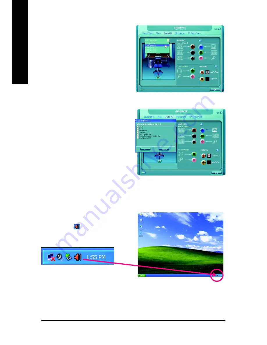
STEP 3:
Connect a speaker or headphone to the rear Line
Out jack, a small window will pop up and ask you
what type of equipment is connected. Choose
Headphone
or
Line Out
depending on the device
connected and click
OK
. The 2-channel audio setup
is completed.
STEP 2:
In the Audio Control Panel, click the
Audio I/O
tab.
In the upper left list, click
2CH Speaker
.
Setting Up 4-Channel Audio
STEP 1 :
After installation of the audio driver, you should find
an Audio Manager icon in your system tray (you
can also find the icon in Control Panel). Double-
click the icon to open the Audio Control Panel.
Summary of Contents for GA-945PLM-(D)S2
Page 28: ...GA 945PLM D S2 rev 2 1 Motherboard 28 English...
Page 50: ...GA 945PLM D S2 rev 2 1 Motherboard 50 English...
Page 54: ...GA 945PLM D S2 rev 2 1 Motherboard 54 English...
Page 74: ...GA 945PLM D S2 rev 2 1 Motherboard 74 English...
Page 75: ...Appendix 75 English...
Page 76: ...GA 945PLM D S2 rev 2 1 Motherboard 76 English...
Page 77: ...Appendix 77 English...
Page 80: ...80 English...


