


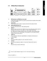


Hardware Installation
- 25 -
English
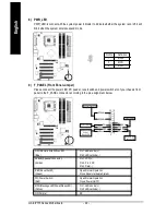
Pin No.
Definition
1
VCC
2
NC
3
IRRX
4
GND
5
IRTX
6
NC
7
CIRRX
8
+5VSB
9
CIRTX
10
NC
14) IR_CIR
Make sure the pin 1 on the IR device is aling with pin one the connector. To enable the IR/CIR function
on the board, you are required to purchase an option IR/CIR module. To use IR function only, please
connect IR module to Pin1 to Pin5. Be careful with the polarity of the IR/CIR connector. Check the pin
assignm ent carefully while you connect the IR/CIR cable, incorrect connection between the cable and
connector will make the device unable to work or even damage it. For optional IR/CIR cable, please
contact your local dealer.
1
5
6
1 0
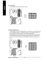
15) F_ USB1 / F_USB2 (Front USB Connector)
Be careful with the polarity of the front USB connector. Check the pin assignment carefully while
you connect the front USB cable, incorrect connection between the cable and connector will make
the device unable to work or even damage it. For optional front USB cable, please contact your
local dealer.
2
1 0
1
9
Pin No.
Definition
1
Power
2
Power
3
USB DX-
4
USB Dy-
5
USB DX+
6
USB Dy+
7
GND
8
GND
9
No Pin
10
NC
Summary of Contents for GA-8IP775 Series
Page 2: ...Motherboard GA 8IP775 GA 8IP775 G Sep 10 2004 Sep 10 2004 Motherboard GA 8IP775 GA 8IP775 G ...
Page 8: ... 8 ...
Page 50: ...GA 8IP775 Series Motherboard 50 English ...
Page 54: ...GA 8IP775 Series Motherboard 54 English ...
Page 77: ...Appendix 77 English ...


