


GA-8IP775 Series Motherboard
- 22 -
English
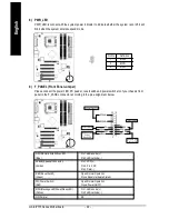
8) PWR_LED
PWR_LED is connect with the system power indicator to indicate whether the system is on/off. It will
blink when the system enters suspend mode.
1
Pin No.
Definition
1
MPD+
2
MPD-
3
MPD-
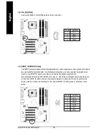
9) F_PANEL (Front Panel Jumper)
Please connect the power LED, PC peaker, reset switch and power switch etc of your chassis front
panel to the F_PANEL connector according to the pin assignment below.
HD (IDE Hard Disk Active LED)
Pin 1: LED anode(+)
(Blue)
Pin 2: LED cathode(-)
SPEAK (Speaker Connector)
Pin 1: VCC(+)
(Amber)
Pin 2- Pin 3: NC
Pin 4: Data(-)
RES (Reset Switch)
Open: Normal Operation
(Green)
Close: Reset Hardware System
PW (Power Switch)
Open: Normal Operation
(Red)
Close: Power On/Off
MSG(Message LED/Power/Sleep LED)
Pin 1: LED anode(+)
(Yellow)
Pin 2: LED cathode(-)
NC( Purple)
NC
1
2
1 9
2 0
HD-
HD+
RES+
RE S-
NC
SPEAK-
MSG-
MSG+
PW-
PW+
SPEAK+
Me ssa ge LED/
Po we r/
Sle ep L ED
Po wer Switch
Spe aker Connector
IDE Hard Di sk
Acti ve L ED
Re set Switch
Summary of Contents for GA-8IP775 Series
Page 2: ...Motherboard GA 8IP775 GA 8IP775 G Sep 10 2004 Sep 10 2004 Motherboard GA 8IP775 GA 8IP775 G ...
Page 8: ... 8 ...
Page 50: ...GA 8IP775 Series Motherboard 50 English ...
Page 54: ...GA 8IP775 Series Motherboard 54 English ...
Page 77: ...Appendix 77 English ...


