


Hardware Installation
- 25 -
English
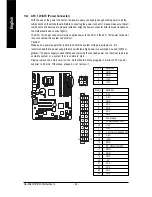
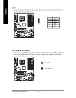
3/4/5) CPU_FAN / SYS_FAN / PWR_FAN (Cooler Fan Power Connector)
The cooler fan power connector supplies a +12V power voltage via a 3-pin/4-pin(only for CPU_FAN)
power connector and possesses a ful-proof connection design.
Most coolers are designed with color-coded power connector wires. A red power connector wire
indicates a positive connection and requires a +12V power voltage. The black connector wire is the
ground wire (GND).
Please remember to connect the power to the cooler to prevent system overheating and failure.
Caution!
Please remember to connect the power to the CPU fan to prevent CPU overheating and failure.
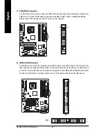
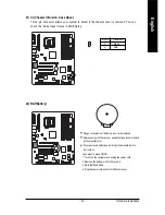
6) NB_FAN (Chip Fan Connector)
If you installed wrong direction, the chip fan will not work. Sometimes will damage the chip fan.
(Usually black cable is GND)
Pin No.
Definition
1
+12V
2
GND
Pin No.
Definition
1
GND
2
+12V
3
Sense
4
Speed Control
(Only for CPU_FAN)
1
CPU_FAN
PWR_FAN
1
1
SYS_FAN
1
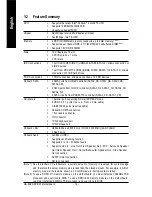
Summary of Contents for GA-8AENXP-DW
Page 2: ...Motherboard GA 8AENXP DW Jan 15 2005 Jan 15 2005 ...
Page 11: ... 11 ...
Page 12: ... 12 ...
Page 34: ...GA 8AENXP DW Motherboard 34 English ...
Page 58: ...GA 8AENXP DW Motherboard 58 English ...
Page 96: ...GA 8AENXP DW Motherboard 96 English ...
Page 97: ...Appendix 97 English ...
Page 98: ...GA 8AENXP DW Motherboard 98 English ...
Page 99: ...Appendix 99 English ...
Page 100: ...GA 8AENXP DW Motherboard 100 English ...
Page 101: ...Appendix 101 English ...