background image

- 68 -

GA-7VM400M(F)-P Motherboard

English

SPDIF Output Device (Optional Device)

3. Connect SPDIF to the SPDIF decoder.

1. Connect the SPDIF output device to the rear

bracket of PC,  and fix it with screw.

2. Connect SPDIF device to the m otherboard.

A "SPDIF output" device is available on the
motherboard. Cable with rear bracket is provided
and could link to the "SPDIF output" connector (As
picture.) For the further linkage to decoder, rear
bracket provides coaxial cable and Fiber
connecting port.

Summary of Contents for GA-7VM400M-P

Page 1: ...mper The factory default for this card is 2X 3 3V The GA 7VM400M F P motherboards might not function properly if you install thiscardwithout switching thejumperto4X 1 5V modeinit Example 2 SomeATi Rage 128 Pro graphics cards made by Power Color the graphics card manufacturer some SiS 305 cards their golden finger is compatible with2X 3 3V 4X 1 5V modeAGPslot but they support 2X 3 3V only The GA 7V...

Page 2: ...ent to update the information contained herein M Third party brands and names are the property of their respective owners M Please do not remove any labels on motherboard this may void the warranty of this motherboard M Due to rapid change in technology some of the specifications might be out of date before publication of this booklet ...

Page 3: ...al commercial and light industry o EN 55015 Limits and methods of measurement of radio disturbance characteristics of fluorescent lamps and luminaries Generic emission standard Part 2 Industrialenvironment o EN 55081 2 Immunity from radio interference of broadcast receiversand associated equipment Generic emission standard Part 2 Industrialenvironment o EN 55082 2 T EN 55022 Limits and methods of ...

Page 4: ...ations This device complies with part 15 of the FCC Rules Operation is subject to the following two conditions 1 This device may not causeharmful and 2 thisdevicemust accept anyinferencereceived including that maycause undesired operation Representative Person s Name Signature Eric Lu Supplementary Information Model Number 17358 Railroad Street City of Industry CA 91748 G B T INC U S A 818 854 933...

Page 5: ...USER S MANUAL GA 7VM400M F P AMD Socket AProcessor Motherboard AMD Athlon Athlon XP Duron Socket A Processor Motherboard Rev 1002 12ME 7VM400MFP 1002 ...

Page 6: ...1 1 CPU Speed Setup 11 Step1 2 CPU Installation 12 Step1 3 CPU Cooling Fan Installation 13 Step 2 Install memory modules 14 Step 3 Install expansion cards 16 Step 4 Connect ribbon cables cabinet wires and power supply 17 Step 4 1 I O Back Panel Introduction 17 Step 4 2 Connectors Introduction 19 Chapter 3 BIOS Setup 31 The Main Menu For example BIOS Ver D2b 32 Standard CMOS Features 34 Advanced BI...

Page 7: ...Fail Safe Defaults 51 Load Optimized Defaults 52 Set Supervisor User Password 53 Save Exit Setup 54 Exit Without Saving 55 Chapter 4 Technical Reference 57 BIOSTM Introduction 57 Easy TuneTM 4 Introduction 58 Flash BIOS Method Introduction 59 2 4 6 Channel Audio Function Introuction 63 Chapter 5 Appendix 71 ...

Page 8: ...the base and there are no slots to attach the spacers do not become alarmed you can still attach the spacers to the mounting holes Just cut the bottom portion of the spacers the spacer may be a little hard to cut off so be careful of your hands In this way you can still attach the motherboard to the base without worrying about short circuits Sometimes you may need to use the plastic springs to iso...

Page 9: ... supports 33MHz PCI 2 2 compliant On Board IDE y 2 IDE bus master UDMA33 ATA66 ATA100 ATA133 IDE ports for up to 4 ATAPI devices y Supports PIO mode3 4 UDMA33 ATA66 ATA100 ATA133 IDE ATAPI CD ROM Onboard SATA y 2 Serial ATA connections Note1 Hardware Monitor y CPU System Fan Revolution detect y CPU System temperature detect y System Voltage Detect On Board Peripherals y 1 Floppy port supports 2 FD...

Page 10: ... PS 2 Mouse power on y External Modem wake up y STR Suspend To RAM y AC Recovery y Poly fuse for keyboard over current protection y USB KB Mouse wake up from S3 y Support Thermal shutdown function y Supports BIOS y Supports EasyTune 4 Overclocking y Over Clock DDR AGP CPU PCI by BIOS Please set the CPU host frequency in accordance with your processor s specifications We don t recommend you to set ...

Page 11: ... F2_1394 F1_1394 F_PANEL F_USB2 SUR_CEN SPDIF_IO PWR_LED AC97 GAME COMB GA 7VM400M F SOCKETA FDD IDE1 IDE2 VGA RTL8100C BIOS CI TSB43AB23 IT8705 BAT VT8237 VIA KM400 PCI1 PCI2 PCI3 DDR1 AGP SW1 CD_IN DDR2 F_AUDIO AGP 8X SYS_FAN MIC_IN USB LAN LINE_IN LINE_OUT For GA 7VM400MF P only BZ USB SATA1 SATA0 ...

Page 12: ... 66 100 133 IDE Channels RTL8100C IT8705 24 MHz 33 MHz Game Port Floppy LPT Port PS 2 KB Mouse 2 COM Ports MIC LINE IN LINE OUT AMD K7TM Host CUP 6 Channel CODEC TSB43AB23 IEEE1394 200 266 333MHz DDR BIOS AGPCLK 66MHz HCLK 100 133 166MHz CLK GEN HCLK 100 133 166MHz CPUCLK 100 133 166MHz AGPCLK 66MHz PCICLK 33MHz USBCLK 48MHz 14 318 MHz 33 MHz PCI BUS 33MHz 66MHz V_Link V_Link 66MHz VGA Port For GA...

Page 13: ...Introduction 9 English ...

Page 14: ...he power cable to the power outlet Continue with the BIOS software installation To set up your computer you must complete the following steps Step 1 Set system Switch SW1 Step 2 Install the Central Processing Unit CPU Step 3 Install memory modules Step 4 Install expansion cards Step 5 Connect ribbon cables cabinet wires and power supply P Step 3 Step 5 Step 2 Step 5 Step 1 Step 4 ...

Page 15: ...U Step1 1 CPU Speed Setup The CPU FSB can be switched by SW1 and refer to below table O ON X OFF Default Setting 100MHz SW1 CPU CLOCK 100MHz 133 166 1 ON OFF You must set SW1 to 100MHz when you used FSB 200MHz CPU 100MHz Fix FSB 200MHz CPU 133 166MHz Support FSB 266 333MHz CPU P SW1 1 ON ...

Page 16: ...r 2 Locate Pin 1 in the socket and look for a golden cut edge on the CPU upper corner Then insert the CPU into the socket Before installing the processor adhere to the following warning 1 Please make sure the CPU type is supported by the motherboard 2 If you do not match the CPU socket Pin 1 and CPU cut edge well it will cause improper installation Please change the insert orientation ...

Page 17: ...e 1 Press down the CPU socket lever and finish CPU installation 1 Please use AMD approved cooling fan 2 We recommend you to apply the thermal paste to provide better heat conduction between your CPU and Cooling Fan 3 Make sure the CPU fan power cable is plugged in to the CPU fan connector this completes the installation Please refer to CPU cooling fan user s manual for more detail installation pro...

Page 18: ...the insert orientation The motherboard has 2 dual inline memory module DIMM sockets The BIOS will automatically detects memory type and size To install the memory module just push it vertically into the DIMM Slot The DIMM module can only fit in one direction due to the notch Memory size can vary between sockets Support Unbuffered DDR DIMM Sizes type 64 Mbit 2Mx8x4 banks 64 Mbit 1Mx16x4 banks 128 M...

Page 19: ...e through reading and writing at both the rising and falling edge of the clock achieving data bandwidth 2X greater than PC133 when running with the same DRAM clock frequency With peak band width of 2 664GB per second DDR memory enables system OEMs to build high performance and low latency DRAM subsystems that are suitable for servers workstations high end PC s and value desktop SMA systems With a ...

Page 20: ...elated expansion card s instruction document before install the expansion card into the computer 2 Remove your computer s chassis cover necessary screws and slot bracket from the computer 3 Press the expansion card firmly into expansion slot in motherboard 4 Be sure the metal contacts on the card are indeed seated in the slot 5 Replace the screw to secure the slot bracket of the expansion card 6 R...

Page 21: ...n Female PS 2 Keyboard Connector 6 pin Female Y USB LANConnector Before you connect your device s into USB connector s please make sure your device s such as USB keyboard mouse scanner zip speaker etc Have a standard USB interface Also make sure your OS supports USB controller If your OS does not support USB controller please contact OS vendor for possible patch or driver upgrade For more informat...

Page 22: ...oose for hardware connection Method1 Connect Front Speaker to Line Out Connect Rear Speaker to Line In Connect Center and Subwoofer to MIC Out Method2 You can refer to page 25 and contact your nearest dealer for optional SUR_CEN cable ZParallel Port Serial Port and VGA Port LPT COMA VGA This connector supports 1 standard COM port 1 Parallel port and 1 VGA port Device like printer can be connected ...

Page 23: ... For GA 7VM400MF P only P 3 8 4 1 2 9 10 17 16 11 20 5 15 13 14 12 18 7 6 1 CPU_FAN 12 CD_IN 2 SYS_FAN 13 SPDIF_IO 3 ATX 14 F_USB1 F_USB2 4 IDE1 IDE2 15 COMB 5 FDD 16 GAME 6 RAM_LED 17 F1_1394 7 F_PANEL 18 F2_1394 8 PWR_LED 19 SATA0 SATA1 9 BAT 20 CI 10 F_AUDIO 11 SUR_CEN 19 ...

Page 24: ...e CPU from running under abnormal condition or damaged by overheating The CPU fan connector supports Max current up to 600 mA 2 SYS_FAN System FAN Connector This connector allows you to link with the cooling fan on the system case to lower the system temperature P Pin No Definition 1 GND 2 12V 3 Sense 1 P Pin No Definition 1 GND 2 12V 3 Sense 1 ...

Page 25: ...e mainboard P Pin No Definition 1 3 3V 2 3 3V 3 GND 4 VCC 5 GND 6 VCC 7 GND 8 Power Good 9 5V SB stand by 5V 10 12V 11 3 3V 12 12V 13 GND 14 PS_ON softOn Off 15 GND 16 GND 17 GND 18 5V 19 VCC 20 VCC 1 10 20 11 4 IDE1 IDE2 IDE1 IDE2 Connector Please connect first harddisk to IDE1 and connect CDROM to IDE2 The red stripe of the ribbon cable must be the same side with the Pin1 P IDE2 IDE1 1 39 2 40 ...

Page 26: ...K 720K 1 2M 1 44M and 2 88Mbytes floppy disk types The red stripe of the ribbon cable must be the same side with the Pin1 1 34 2 33 P 6 RAM_LED Do not remove memory modules while RAM LED is on It might cause short or other unexpected damages due to the standby voltage Remove memory modules only whenAC Power cord is disconnected P ...

Page 27: ...tem PW Soft Power Connector Open Normal Operation Close Power On Off MSG Message LED Power Sleep LED Pin 1 LED anode Pin 2 LED cathode NC NC 7 F_PANEL 2x10 pins connector Please connect the power LED PC peaker reset switch and power switch etc of your chassis front panel to the F_PANEL connector according to the pin assignment above P 8 PWR_LED PWR_LED is connect with the system power indicator to...

Page 28: ...ter P 10 F_AUDIO F_AUDIO Connector If you want to use Front Audio connector you must remove 5 6 9 10 Jumper In order to utilize the front audio header your chassis must have front audio connector Also please make sure the pin assigment on the cable is the same as the pin assigment on the MB header To find out if the chassis you are buying support front audio connector please contact your dealer Pl...

Page 29: ...ntact your nearest dealer for optional SUR_CEN cable P Pin No Definition 1 SUR OUTL 2 SUR OUTR 3 GND 4 No Pin 5 CENTER_OUT 6 BASS_OUT 1 5 6 2 12 CD_IN CD IN Black Connect CD ROM or DVD ROM audio out to the connector P Pin No Definition 1 CD L 2 GND 3 GND 4 CD_R 1 ...

Page 30: ...ptional SPDIF_IO cable please contact your local dealer P Pin No Definition 1 VCC 2 No Pin 3 SPDIF 4 SPDIFI 5 GND 6 GND 1 6 2 5 14 F_ USB1 F_USB2 Front USB Connector Yellow Be careful with the polarity of the front USB connector Check the pin assignment while you connect the front USB cable Please contact your nearest dealer for optional front USB cable Be careful with the polarity of the F_USB co...

Page 31: ...rest dealer for optional COMB cable Pin No Definition 1 NDCDB 2 NSINB 3 NSOUTB 4 NDTRB 5 GND 6 NDSRB 7 NRTSB 8 NCTSB 9 NRIB 10 No Pin P 1 9 10 2 16 GAME GAME Connector This connector supports joystick MIDI keyboard and other relate audio devices 16 2 1 15 Pin No Definition 1 VCC 2 GRX1_R 3 GND 4 GPSA2 5 VCC 6 GPX2_R 7 GPY2_R 8 MSI_R 9 GPSA1 10 GND 11 GPY1_R 12 VCC 13 GPSB1 14 MSO_R 15 GPSB2 16 No ...

Page 32: ...tion 1 TPA2 2 TPA2 3 GND 4 GND 5 TPB2 6 TPB2 7 Power 8 Power 9 No Pin 10 GND 2 9 10 For GA 7VM400MF P only 18 F2_1394 IEEE 1394 Connector Please Note Serial interface standard set by Institute of Electrical and Electronics Engineers which has features like high speed high bandwidth and hot plug Be careful with the polarity of the IEEE1394 connector Check the pin assignment carefully while you conn...

Page 33: ...TA1 please Enable OnChip Serial ATA item Then install the correct driver to have proper operation For details please refer to the VT8237_SATA_Manual pdf at http www gigabyte com tw 7 1 Pin No Definition 1 GND 2 TXP 3 TXN 4 GND 5 RXN 6 RXP 7 GND P 20 CI CASE OPEN This 2 pin connector allows your system to enable or disable the case open item in BIOS if the system case begin remove P Pin No Definiti...

Page 34: ... 30 GA 7VM400M F P Motherboard English ...

Page 35: ... CONTROL KEYS Chapter 3 BIOS Setup á Move to previous item â Move to next item ß Move to the item in the left hand à Move to the item in the right hand Enter Select item Esc Main Menu Quit and not save changes into CMOS Status Page Setup Menu and Option Page Setup Menu Exit current page and return to Main Menu PgUp Increase the numeric value or make changes PgDn Decrease the numeric value or make ...

Page 36: ...ions for the highlighted item To exit the Help Window press Esc The Main Menu For example BIOS Ver D2b Once youenterAward BIOS CMOS SetupUtility the Main Menu Figure 1 will appearon the screen The MainMenuallows youto selectfrom eight setup functions andtwo exitchoices Usearrow keys to select among the items and press Enter to accept or enter the sub menu Figure 1 MainMenu CMOS Setup Utility Copyr...

Page 37: ...system parameters which the system would be in safe configuration l LoadOptimizedDefaults Optimized Defaults indicates the value of the system parameters which the system would be in better performance configuration l LoadTop Performance Defaults Top Performance Defaults indicates the value of the system parameters which the system would be in best performance configuration l Set Supervisor passwo...

Page 38: ...13 00 00 CMOS Setup Utility Copyright C 1984 2003 Award Software Standard CMOS Features Date mm dd yy Tue Aug 13 2002 Item Help Time hh mm ss 22 31 24 Me n uL e v e l u Change the day month IDE Primary Master None year IDE Primary Slave None IDE Secondary Master None Week IDE Secondary Slave None Sun to Sat Drive A 1 44M 3 5 in Month Drive B None Jan to Dec Floppy 3 Mode Support Disabled Day Halt ...

Page 39: ...unit is Mega Bytes Access Mode The options are Auto Large LBA Normal Cylinder The cylinder number of hard disk Head The read Write head number of hard disk Precomp The cyliner number at which the disk driver changes the write current Landing Zone The cylinder number that thedisk driver heads read write are seated when the disk drive is parked SECTORS The sector number of each track define on the h...

Page 40: ...top for all other errors Default value All But Diskette The system boot will not stop for a disk error it will stop for all other errors All But Disk Key The system boot will not stop for a keyboard or disk error it will stop for all other errors Memory The category is display only which is determined by POST Power On Self Test of the BIOS Base Memory The POST of the BIOS will determine the amount...

Page 41: ...e priority by LAN USB CDROM Select your boot device priority by USB CDROM USB ZIP Select your boot device priority by USB ZIP USB FDD Select your boot device priority by USB FDD CMOS Setup Utility Copyright C 1984 2003 Award Software Advanced BIOS Features First Boot Device Floppy Item Help Second Boot Device HDD 0 Me n uL e v e l u Third Boot Device CD ROM Select Boot Device Password Check Setup ...

Page 42: ...device priority by ZIP Disabled Disable this function PasswordCheck Setup The system will boot but will not access to Setup page if the correct password is not entered at the prompt Default value System The system will not boot and will not access to Setup page if the correct password is not entered at the prompt ...

Page 43: ...bled Enable onboard IDE USB Mouse Support Disabled Channel Onboard H W LAN Enabled Onboard H W 1394 Enabled Disabled Onbard LAN Boot ROM Disabled Disable onboard IDE Onboard Serial Port 1 3F8 IRQ4 Channel Onboard Serial Port 2 2F8 IRQ3 Onboard Parallel Port 378 IRQ7 Parallel Port Mode SPP Game Port Address 201 Mdi Port Address 330 Midi Port IRQ 10 higf Move Enter Select PU PD Value F10 Save ESC Ex...

Page 44: ...ATA MIf you want to find the detailed information for SATA RAID setup installation please download VT8237_SATA_Manual pdf at http www gigabyte com tw Disabled Disable SATA controller Enabled Enable SATA controller Default Value AC97 Audio Enabled Enable OnchipAC97 controller Default value Disabled Disable OnchipAC97 controller USB 1 1 Controller MDisable this option if you are not using the onboar...

Page 45: ... value Disable Disable onboard this function Onboard LAN Boot ROM This function decide whether to invoke the boot ROM of the onboard LAN chip Disabled Disable this function Default Value Enabled Enable this function OnboardSerial Port 1 Auto BIOS will automatically setup the port 1 address 3F8 IRQ4 EnableonboardSerial port1and address is 3F8 Using IRQ4 Defaultvalue 2F8 IRQ3 Enable onboard Serial p...

Page 46: ... address is 278 Using IRQ5 3BC IRQ7 Enable onboard LPT port and address is 3BC Using IRQ7 Disabled Disable onboard parallel port Parallel Port Mode MThis feature allows you to connect with an advanced print via the port mode it supports SPP Using Parallel port as Standard Parallel Port using IRQ7 Default Value EPP Using Parallel port as Enhanced Parallel Port IRQ5 ECP Using Parallel port as Extend...

Page 47: ... value CMOS Setup Utility Copyright C 1984 2003 Award Software Power Management Setup ACPI Suspend Type S1 POS Item Help x USB Device Wake Up From S3 Disabled Menu Level u Power LED in S1 state Blinking S1 Soft Off by PWRBTN Instant off Set suspend type to AC Back Function Soft Off Power On Suspend under Keyboard Power On Disabled ACPI OS Mouse Power On Disabled PME Event Wake Up Enabled S3 ModemR...

Page 48: ...eforeAC lost Soft Off Always in Off state whenAC back Default value Full On Always power on the system whenAC back Keyboard Power On This feature allows you to set the method for powering on the system The option Password allows you to set up to 8 alphanumeric characters to power on the system The option Keyboard 98 allows you to use the standard keyboard 98 to power on the system Password Enter f...

Page 49: ...d connector Only enabledthe feature by PME Event Wake up MAn incoming call via modem awakes the system from its soft off mode MWhen set at Enabled an input signal comes from the other client Server on the LAN awaks the system from a soft off state if connected over LAN Disabled Disable Modem Ring On Wake On LAN function Enabled Enable Modem Ring On Wake On LAN function Default Value Resume byAlarm...

Page 50: ...10 11 12 14 15 to PCI2 PCI3 IRQAssignment Auto Auto assign IRQ to PCI 3 Default value 3 4 5 7 9 10 11 12 14 15 Set 3 4 5 7 9 10 11 12 14 15 to PCI3 CMOS Setup Utility Copyright C 1984 2003 Award Software PnP PCI Configurations PCI 1 IRQ Assignment Auto Item Help PCI 2 IRQ Assignment Auto Menu Level u PCI 3 IRQ Assignment Auto Decice s using this INT USB 1 1 Host Cntrlr Bus 0 Dev16 Func 1 higf Move...

Page 51: ...OS Setup Utility Copyright C 1984 2003 Award Software PC Health Status Reset Case Open Status Disabled Item Help Case Opened No Menu Level u Vcore 1 772V Disabled DDR Vtt 1 248V Don t reset case 3 3V 3 280V open status 5V 4 919 V 12V 11 968V Enabled 5VSB 5 053V Clear case open Current System Temperature 31 C status at next boot Current CPU Temperature 45 C Current CPU FAN Speed 4440RPM Current SYS...

Page 52: ...ent System CPUTemperature e Detect System CPU Temp automatically Current CPUFAN SYSTEMFAN Speed RPM Detect Fan speed status automatically Fan Fail Warning CPU SYSTEM Disabled Don t monitor current fan speed Default value Enabled Alarm when stops ...

Page 53: ...auto detect PCI DIMM Clk Enabled Enable auto detect PCI DIMM Clk Default value SpreadSpectrum Disabled Disable clock spread spectrum Enabled Enable clock spread spectrum Default value CPUHost AGP PCIClock Default Set CPU Host AGP PCI Clock by default 100 66 33 MHz Set CPU Host AGP PCI Clock to 100 66 33 MHz 102 68 34 MHz Set CPU Host AGP PCI Clock to 102 68 34 MHz 105 70 35 MHz Set CPU Host AGP PC...

Page 54: ...y issue Please set DRAM Clock according to your requirement If youuse DDR266 DRAM module please set DRAM Clock MHz to 133 DDR266 Ifyou use DDR333 DRAM module please set DRAM Clock MHz to 166 DDR333 If you use Incorrect using it may cause your system broken For power End User use only Auto Auto setting Memory frequency Default value ...

Page 55: ...1984 2003 Award Software Standard CMOS Features Load Fail Safe Defaults Advanced BIOS Features Load Optimized Defaults Integrated Peripherals Set Supervisor Password Power Management Setup Set User Password PnP PCI Configurations Save Exit Setup PC Health Status Exit Without Saving Frequency Voltage Control ESC Quit higf Select Item F8 Q Flash F10 Save Exit Setup Load Fail Safe Defaults Figure 11 ...

Page 56: ...right C 1984 2003 Award Software Standard CMOS Features Load Fail Safe Defaults Advanced BIOS Features Load Optimized Defaults Integrated Peripherals Set Supervisor Password Power Management Setup Set User Password PnP PCI Configurations Save Exit Setup PC Health Status Exit Without Saving Frequency Voltage Control ESC Quit higf Select Item F8 Q Flash F10 Save Exit Setup Load Optimized Defaults Fi...

Page 57: ... function When enabled theSupervisor password is required for entering theBIOS Setup program and having full configuration fields the User password is required to access only basic items If youselect System at Security Option inAdvance BIOS Features Menu you will beprompted for the password every time the system is rebooted or any time you try to enter Setup Menu If you select Setup at Security Op...

Page 58: ...right C 1984 2003 Award Software Standard CMOS Features Load Fail Safe Defaults Advanced BIOS Features Load Optimized Defaults Integrated Peripherals Set Supervisor Password Power Management Setup Set User Password PnP PCI Configurations Save Exit Setup PC Health Status Exit Without Saving Frequency Voltage Control ESC Quit higf Select Item F8 Q Flash F10 Save Exit Setup Save Data to CMOS Save to ...

Page 59: ...4 2003 Award Software Standard CMOS Features Load Fail Safe Defaults Advanced BIOS Features Load Optimized Defaults Integrated Peripherals Set Supervisor Password Power Management Setup Set User Password PnP PCI Configurations Save Exit Setup PC Health Status Exit Without Saving Frequency Voltage Control ESC Quit higf Select Item F8 Q Flash F10 Save Exit Setup Abandon all Data Quit Without Saving ...

Page 60: ... 56 GA 7VM400M F P Motherboard English ...

Page 61: ...te software Itcould helpyou to download the BIOSfrom internetand update it Notlike the otherBIOS update software it s a Windowsutility With the help of BIOS BIOS updating is no morethan a click Besides no matterwhich mainboardyou areusing ifit s a Gigabyte s product BIOShelp youto maintainthe BIOS This utilitycould detectyourcorrectmainboard modeland help you to choose the BIOSaccordingly Itthen d...

Page 62: ...then overdrive CPU speedautomaticallywiththe resultbeingshown in thecontrolpanel Ifusersprefer Overclock bythem there isalso anotherchoice Click Advanced Mode to enjoy sportdrive class Overclocking user interface Advanced Mode allows users to change the system bus AGP Memory working frequency in small increments to getultimate system performance Itoperates in coordination with Gigabyte motherboard...

Page 63: ... Q Flash Utility CMOS Setup Utility Copyright C 1984 2003 Award Software Standard CMOS Features Load Fail Safe Defaults Advanced BIOS Features Load Optimized Defaults Integrated Peripherals Set Supervisor Password Power Management Setup Set User Password PnP PCI Configurations Save Exit Setup PC Health Status Exit Without Saving Frequency Voltage Control ESC Quit higf Select Item F8 Q Flash F10 Sa...

Page 64: ...to update BIOS Enter to contiune Or ESC otabort COPY BIOS Completed Pass Please pressany keyto continue Press Enter toRun Load BIOS From Floppy In the A drive insertthe BIOS diskette then Press Enterto Run XXXX XX 256K TotalSize 1 39M Free Size 1 14M F5 Refresh DEL Delete ESC Return Main 1File s found Where XXXX XXis name ofthe BIOSfile ...

Page 65: ...ndsteps I Update BIOS through Internet a Click InternetUpdate icon b Click Update New BIOS icon c Select BIOSTM sever d Selectthe exactmodelnameonyourmotherboard e System willautomatically download and update the BIOS 3 1 4 2 2 Click Start Programs GIGABYTE BIOS 3 Click P 4 Click here 5 Please select BIOS sever site then Click OK 1 Click BIOS Presshere ...

Page 66: ...ash ROM Intheverybeginning thereis Aboutthis program icon shownin dialog box Itcan help you check outwhichkindofmotherboardandwhich brandofFlashROMaresupported Note a Inmethod I ifitshows twoormore motherboard s modelnames to be selected please make sure yourmotherboard smodelnameagain Selectingwrong modelname willcause the systemunbooted b Inmethod II be surethatmotherboard s modelname in BIOS un...

Page 67: ...e the speaker with amplifier to acqiire the best sound effect if the stereo output is applied STEP 1 Connect the stereo speakers or earphone to Line Out STEP 2 After installation of the audio driver you ll find an icon on the taskbar s status area Click the audio icon Sound Effect from the windows tray at the bottom of the screen The installation of windows 98SE 2K ME XP is very simple Please foll...

Page 68: ...for 4 speakers out put Disable Only SURROUND KIT and press OK When the Environment settings is None the sound would be performed as stereo mode 2 channels output Please select the other settings for 4 channels output STEP 2 After installation of the audio driver you ll find an icon on the taskbar s status area Click the audio icon Sound Effect from the windows tray at the bottom of the screen Line...

Page 69: ...nter Subwoofer channels to MIC In Basic 6 Channel Analog Audio Output Mode STEP 2 After installation of the audio driver you ll find an icon on the taskbar s status area Click the audio icon Sound Effect from the windows tray at the bottom of the screen STEP 3 Select Speaker Configuration and choose the 6 channels for 5 1 speakers out put Disable Only SURROUND KIT and pess OK Line Out Line In MIC ...

Page 70: ...vice Audio Combo Kit provides SPDIF output port optical coaxis and SURROUND KIT Rear R L CEN Subwoofer SURROUND KIT access analog output to rear channels and Center Subwoofer channels It is the best solution if you need 6 channel output Line In and MIC at the same time SURROUND KIT is included in the GIGABYTE unique Audio Combo Kit as picture STEP 2 Connect the SURROUND KIT to SUR_CEN on the M B ...

Page 71: ...UND KIT s REAR R L and the Center Subwoofer channels to SURROUND KIT s SUB CENTER STEP 5 Select Speaker Configuration and choose the 6 channels for 5 1 speakers out put Enable Only SURROUND KIT and press OK Whenthe Environmentsettings is None the sound would be performed as stereo mode 2 channels output Please select the other settings for 6 channels output Basic Advanced 6 Channel Analog Audio Ou...

Page 72: ...utput device to the rear bracket of PC and fix it with screw 2 Connect SPDIF device to the motherboard A SPDIF output device is available on the motherboard Cable withrearbracketis provided andcould link to the SPDIFoutput connector As picture For the further linkage to decoder rear bracketprovides coaxialcableandFiber connectingport ...

Page 73: ...Technical Reference 69 English ...

Page 74: ... 70 GA 7VM400M F P Motherboard English ...

Page 75: ...is page shows the drivers that need to be installed for the system Click each item to install the driver manually or switch to the to install the drivers automatically Massage Some device drivers will restart your system automatically After restarting your system the Xpress Install will continue to install other drivers The Xpress Install uses the Click and Forget technology to install the drivers...

Page 76: ...ver for Realtek AC97 codec chipset n VIA 8237 Serial ATA Driver For VIA 8237 SATA Driver n VIA USB 2 0 Controller For VIA VT8233 VT6203 VIA VT8235 VIA VT8237 south bridge Item Description Driver install finished you have to reboot system For USB2 0 driver support under Windows XP operating system please use Windows Service Pack After install Windows Service Pack it will show a question mark in Uni...

Page 77: ...rclocking and hardware monitoring functions n DMI Viewer Windows based utility which is used to browse the DMI SMBIOS information of the system n Face Wizard New utility for adding BIOS logo n BIOS Gigabyte windows flash BIOS utility n Acrobat e Book Useful utility from Adobe n Acrobat Reader Popular utility from Adobe for reading PDF file format documents n Norton Internet Security NIS Integrated...

Page 78: ...ard English SOFTWARE INFORMATION This page list the contects of softwares and drivers in this CD title HARDWARE INFORMATION This page lists all device you have for this motherboard CONTACT US Please see the last page for details ...

Page 79: ...that s why the light is still on Question 3 Why cannot I use all functions in EasyTune 4 Answer The availability of the listed functions in EasyTune 4 depends on the MB chipset If the chipset doesn t support certain functions in EasyTune 4 these functions will be locked automati cally and you will not be able to use them Question 4 Why do I fail to install RAID and ATA drivers under Win 2000 and X...

Page 80: ... Please remember to load Fail Safe Defaults Or Load BIOS Defaults after flashing BIOS However if the system instability still remains please clear CMOS to solve the problem Question 7 Why do I still get a weak sound after turning up the speaker to the maximum volume Answer Please make sure the speaker you are using is equipped with an internal amplifier If not please change another speaker with po...

Page 81: ...eeps Display memory read write failure 9 beeps ROM checksum error 10 beeps CMOS shutdown register read write error 11 beeps Cache memory bad g AWARD BIOS Beep Codes 1 short System boots successfully 2 short CMOS setting error 1 long 1 short DRAM or M B error 1 long 2 short Monitor or display card error 1 long 3 short Keyboard error 1 long 9 short BIOS ROM error Continuous long beeps DRAM error Con...

Page 82: ... device SCSI 3 Integrated Peripherals Onboard H W ATA RAID enable Then it depends on the RAID mode that you need to set RAID to RAID mode or ATA to normal ATA mode in the item named RAID controller function Question 13 How to set in the BIOS to bootup from the IDE SCSI RAID card Answer Please set in the BIOS as follow 1 Advanced BIOS features SATA RAID SCSI boot order SCSI 2 Advanced BIOS features...

Page 83: ...uency ratio voltage and etc are set properly Failure has been excluded Check if the CPU cooling fan attached to CPU properly ls CPU cooling fan power connected to CPU_FAN properly Plug the CPU cooling fan power in the CPU fan connector Plug in the AC power connector Check if the memory install properly into the DIMM slot Yes No Yes Insert and push the memory module vertically into the DIMM slot In...

Page 84: ...gabyte com tw The appropriate response will be provided ASAP Is memory LED on and CPU fan running The problem could be caused by power supply CPU memory or CPU memory socket itself Check if there is display Perhaps your VGA card VGA slot or monitor is defective Turn off the system Reboot after keyboard and mouse have been plugged in Check if keyboard is working properly It is possible that your ke...

Page 85: ...o Contact Person E mail Add Model name Lot Number PCB revision BIOS version O S A S Hardware Mfs Model name Size Driver Utility Configuration CPU Memory Brand Video Card Audio Card HDD CD ROM DVD ROM Modem Network AMR CNR Keyboard Mouse Power supply Other Device Problem Description ...

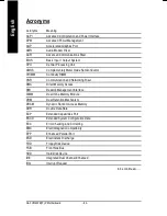
Page 86: ...R Communication and Networking Riser DMA Direct Memory Access DMI Desktop Management Interface DIMM Dual Inline Memory Module DRM Dual Retention Mechanism DRAM Dynamic Random Access Memory DDR Double Data Rate ECP Extended Capabilities Port ESCD Extended System Configuration Data ECC Error Checking and Correcting EMC Electromagnetic Compatibility EPP Enhanced Parallel Port ESD Electrostatic Discha...

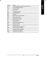
Page 87: ...e MHz Megahertz MIDI Musical Instrument Digital Interface MTH Memory Translator Hub MPT Memory Protocol Translator NIC Network Interface Card OS Operating System OEM Original Equipment Manufacturer PAC PCI A G P Controller POST Power On Self Test PCI Peripheral Component Interconnect RIMM Rambus in line Memory Module SCI Special Circumstance Instructions SECC Single Edge Contact Cartridge SRAM Sta...

Page 88: ... 84 GA 7VM400M F P Motherboard English ...

Page 89: ... 85 English Memo ...

Page 90: ... 86 GA 7VM400M F P Motherboard English ...

Page 91: ... 87 English Memo ...

Page 92: ... 88 GA 7VM400M F P Motherboard English ...

Page 93: ... 89 English Memo ...

Page 94: ... 90 GA 7VM400M F P Motherboard English ...

Page 95: ... 91 English Memo ...

Page 96: ...EB Address http de giga byte com Japan Nippon Giga Byte Corporation WEB Address http www gigabyte co jp U K G B T TECH CO LTD Tel 44 1908 362700 Fax 44 1908 362709 E mail support gbt tech co uk WEB Address http uk giga byte com The Netherlands Giga Byte Technology B V Address Verdunplein 8 5627 SZ Eindhoven The Netherlands Tel 31 40 290 2088 NL Tech Support 0900 GIGABYTE 0900 44422983 0 2 M BE Tec...

Reviews: