BIOS Configuration
4-23
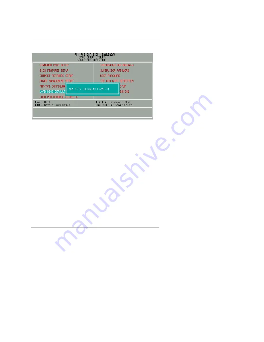
4.10. LOAD BIOS DEFAULTS
Figure 4.7: Load BIOS Defaults
•
Load BIOS Defaults
To load BIOS defaults value to CMOS SRAM, enter "Y". If not, enter "N".
Page 1: ...L KEYS Up arrow Move to previous item Down arrow Move to next item Left arrow Move to the item in the left hand Right arrow Move to the item in the right hand Esc key Main Menu Quit and not save chang...
Page 2: ...ghted item To exit the Help Window press Esc 4 4 THE MAIN MENU Once you enter Award BIOS CMOS Setup Utility the Main Menu Figure 4 1 will appear on the screen The Main Menu allows you to select setup...
Page 3: ...n Load Performance defaults Performance Defaults indicates the value of the system parameters that the system would be in the best performance configuration Integrated peripherals This setup page incl...
Page 4: ...ct the value you want in each item Figure 4 2 Standard CMOS Setup Menu Date The date format is day month date year day The day from Sun to Sat determined by the BIOS and is display only month The mont...
Page 5: ...Such information should be provided in the documentation form your hard disk vendor or the system manufacturer CYLS Number of cylinders HEADS number of heads PRECOMP write precomp LANDZONE Landing zo...
Page 6: ...r up in 40 column mode CGA 80 Color Graphics Adapter power up in 80 column mode MONO Monochrome adapter includes high resolution monochrome adapters Halt on The category determines whether the compute...
Page 7: ...panded Memory Expanded Memory in memory defined by the Lotus Intel Microsoft LIM standard as EMS Many standard DOS applications can not utilize memory above 640 K the Expanded Memory Specification EMS...
Page 8: ...gram to locate the problem The default value is Disabled Enabled Activate automatically when the system boots up causing a warning message to appear when anything attempts to access the boot sector or...
Page 9: ...OST Disabled Normal POST Boot From LAN First The default value is Enabled Enabled Enable Boot From LAN First Disabled Disable Boot From LAN First Auto Boot From LAN First set to Auto You can set Auto...
Page 10: ...s Disabled BIOS will not search for the type of floppy disk drive by track number Note that there will not be any warning message if the drive installed is 360 K Boot Up NumLock Status The default val...
Page 11: ...entered at the prompt M To disable security select PASSWORD SETTING at Main Menu and then you will be asked to enter password Do not type anything and just press Enter it will disable security Once th...
Page 12: ...port No FDD For WIN 95 The default value is No No Function disabled Yes Report No FDD For WIN 95 Video BIOS Shadow It determines whether video BIOS is able to copy to RAM however it is optional from c...
Page 13: ...ault value is SDRAM 10ns Turbo For Turbo DRAM timing operation SDRAM 10ns For SDRAM 10ns DRAM timing operation SDRAM Cycle Length The default value is 3 3 For Slower SDRAM DIMM module 2 For Fastest SD...
Page 14: ...ed Enabled Concurrent PCI Host Disabled Disabled Concurrent PCI Host Video RAM Cacheable The default value is Disabled Disabled Disable this function Enabled Enable this function to get better VGA per...
Page 15: ...Temp will cause system slow down CPU Duty Cycle to 12 5 75 0 Shutdown Temp C F Optional This function will be effective only for the operating systems that support ACPI Function The default value is...
Page 16: ...s No No When CPU Temp overheat then system won t alarm Yes When CPU Temp overheat then system will alarm Fan Fail Alarm Optional CPU POWER PANEL No Fan Fail Alarm Function Disabled Yes Fan Fail Alarm...
Page 17: ...tically 4 8 POWER MANAGEMENT SETUP Figure 4 5 Power Management Setup These two items will show up when RTC Alarm Resume is Enabled Power Management The default value is User Define User Define Set Pow...
Page 18: ...ill turn off V H SYNC when gets into Green mode for Green monitor power saving Blank Screen BIOS will only black monitor when gets into Green mode DPMS Support BIOS will use DPMS Standard to control V...
Page 19: ...he default value is Disable Disable Disable HDD Power Down mode function 1 15 mins Enable HDD Power Down mode between 1 to 15 mins Suspend Mode The default value is Disable Disabled Disable Suspend Mo...
Page 20: ...AN Ring RTC Alarm Resume The default value is Disabled Disabled Disable this function Enabled Enable alarm function to POWER ON system If the RTC Alarm Resume is Enabled Date of Month Alarm 0 31 Time...
Page 21: ...ow up when Resources Controlled By is Manual PNP OS Installed The default value is No Yes Enable PNP OS Installed function No Disable PNP OS Installed function Resources Controlled by The default valu...
Page 22: ...Q 3 4 5 7 9 10 11 12 14 15 DMA 0 1 3 5 6 7 assigned to The default value is Legacy ISA or PCI ISA PnP Legacy ISA The resource is used by Legacy ISA device PCI ISA PnP The resource is used by PCI ISA P...
Page 23: ...BIOS Configuration 4 23 4 10 LOAD BIOS DEFAULTS Figure 4 7 Load BIOS Defaults Load BIOS Defaults To load BIOS defaults value to CMOS SRAM enter Y If not enter N...
Page 24: ...6VA7 4 24 4 11 LOAD PERFORMANCE DEFAULTS Figure 4 8 Load Performance Defaults Load PERFORMANCE Defaults To load PERFORMANCE defaults value to CMOS SRAM enter Y If not enter N...
Page 25: ...s item will show up when Keyboard Power On Multikey is selected Onchip IDE Channel 0 The default value is Enabled Enabled Enabled onboard 1st channel IDE port Disabled Disabled onboard 1st channel IDE...
Page 26: ...he default value is Auto Auto BIOS will automatically detect the IDE HDD Accessing mode Mode0 4 Manually set the IDE Accessing mode Primary Slave PIO for onboard IDE 1st channel The default value is A...
Page 27: ...ect the IDE HDD Accessing mode Disabled Disable UDMA function Primary Slave UDMA The default value is Auto Auto BIOS will automatically detect the IDE HDD Accessing mode Disabled Disable UDMA function...
Page 28: ...ort 1 address 3F8 IRQ4 Enable onboard Serial port 1 and address is 3F8 2F8 IRQ3 Enable onboard Serial port 1 and address is 2F8 3E8 IRQ4 Enable onboard Serial port 1 and address is 3E8 2E8 IRQ3 Enable...
Page 29: ...CP EPP mode PS 2 Mouse Power on The default value is Disabled Disabled Disable PS 2 Mouse Power on Left Double Double Click on PS 2 mouse left button to Power on system Right Double Double Click on PS...
Page 30: ...Type the password again and press Enter To disable password just press Enter when you are prompted to enter password A message PASSWORD DISABLED will appear to confirm the password being disabled Onc...
Page 31: ...11 IDE HDD Auto Detection Type Y will accept the H D D parameter reported by BIOS Type N will keep the old H D D parameter setup If the hard disk cylinder number is over 1024 then the user can select...
Page 32: ...6VA7 4 32 4 15 SAVE EXIT SETUP Figure 4 12 Save Exit Setup Type Y will quit the Setup Utility and save the user setup value to RTC CMOS SRAM Type N will return to Setup Utility...
Page 33: ...BIOS Configuration 4 33 4 16 EXIT WITHOUT SAVING Figure 4 13 Exit Without Saving Type Y will quit the Setup Utility without saving to RTC CMOS SRAM Type N will return to Setup Utility...
Page 34: ......
Page 35: ...later or Windows 98 Bata3 or later If your system version is Win95 or OSR 2 0 You must use the USB support update make sure the update language is the same with your system language to upgrade your sy...
Page 36: ...VIA Chipset Driver Installation A 2 A 1 VIA Patch 95 98 Driver Ver 1 1 Win95 98 ONLY Step By Step Installation STEP 1 STEP 2 Select the VIA Patch 95 98 Driver Ver 1 1 item...
Page 37: ...6VA7 A 3 STEP 3 STEP 4 Click the Next button Click the Next button...
Page 38: ...VIA Chipset Driver Installation A 4 STEP 5 STEP 6 System will restart and start up using the VIA chipset driver Click the Finish button...
Page 39: ...6VA7 A 5 A 2 VIA AGP Driver Ver 3 2 Win95 98 ONLY STEP 1 STEP 2 Select the VIA AGP Driver Ver 3 2 item...
Page 40: ...VIA Chipset Driver Installation A 6 STEP 3 STEP 4 Click the Next button Click the Next button...
Page 41: ...6VA7 A 7 STEP 5 STEP 6 System will restart and start up using the VIA chipset driver Click the Next button Click the Finish button...
Page 42: ...VIA Chipset Driver Installation A 8 A 3 VIA PCI Routing Miniport Driver Ver 1 3 Win98 ONLY STEP 1 STEP 2 Select the VIA PCI Routing Miniport Driver Ver 1 3 item...
Page 43: ...6VA7 A 9 STEP 3 STEP 4 STEP 5 System will restart and start up using the VIA chipset driver Click the Next button Click the Finish button...
Page 44: ...Driver We support two kinds of high performance IDE Bus master Ultra DMA Drivers You could install one of them to enable the DMA operation of your hard disk CD ROM drives Select the Xstore Pro IDE Dri...
Page 45: ...unning Winstone 99 Business Winstone 99 under the Windows NT4 0 operating system the following error message may appear mtrun exe Bad image The application or DLL C WINNT System MSVCRi40 DLL is not a...
Page 46: ......
Page 47: ...technician for additional suggestions You are cautioned that any change or modifications to the equipment not expressly approve by the party responsible for compliance could void Your authority to op...
Page 48: ...apparatus Residual commercial and light industry EN 55015 Limits and methods of measurement EN 55081 2 Generic emission standard Part 2 of radio disturbance characteristics of Industrial environment f...