Gigabyte G-MAX Micro ATX Series User Manual Download Page 9

 G-MAX

TM

 Micro ATX Series User’s Manual 


P. E9 

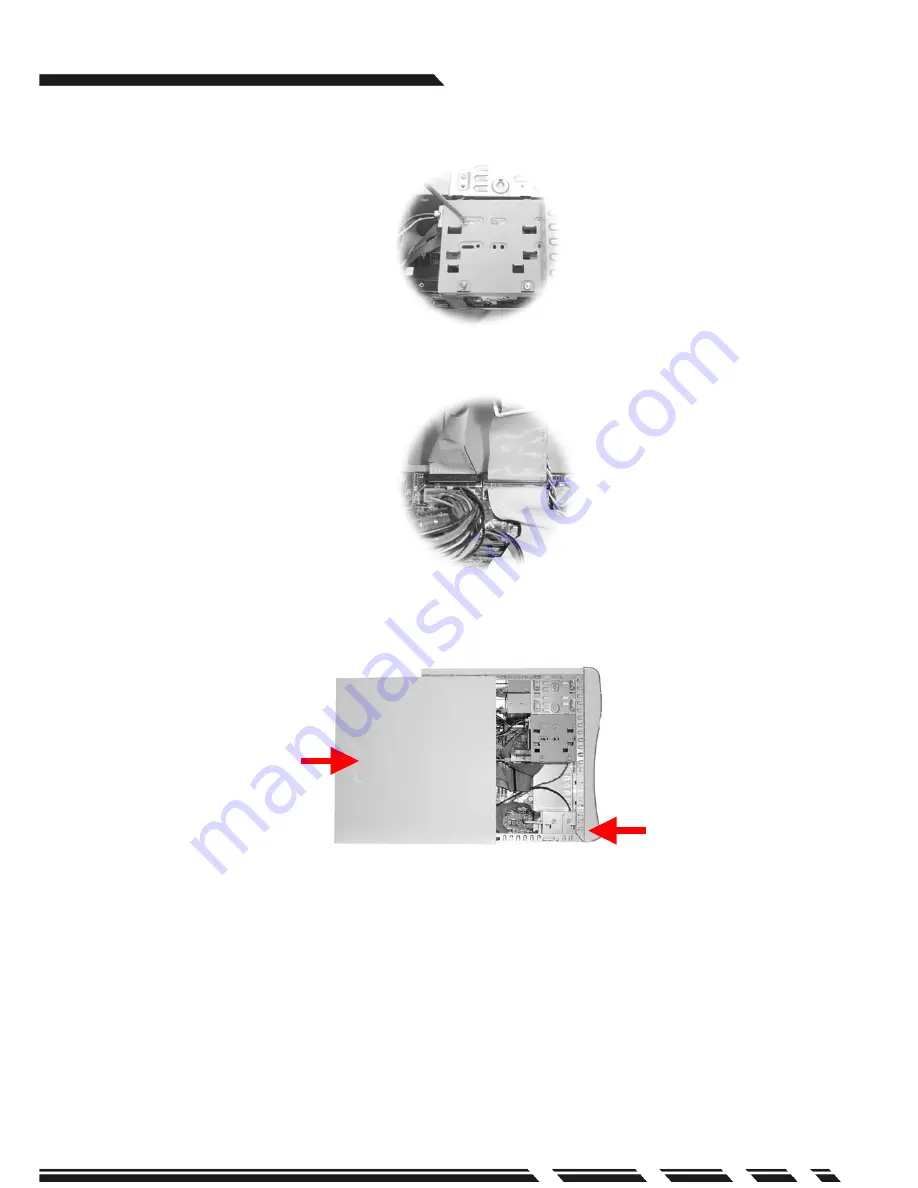
5.Install chassis back to position after completing hard drive installation.   


6.Connect the other end of the IDE connector to the IDE-1 bus on the motherboard.  


7.Check all connections again.   


Put back front panel


Put back side panel

Summary of Contents for G-MAX Micro ATX Series

Page 1: ...y errors or omissions that may appear in this document nor does the author make a commitment to update the information contained herein Third party brands and names are the property of their respectiv...

Page 2: ...rd Place your system unit in a cool clean space to be far away from water heat and dust Before connecting any peripheral equipment please unplug the power cord from the system unit to prevent unexpect...

Page 3: ...G MAX TM Micro ATX Series User s Manual P E3 Software and Manuals Power Cord PC Mouse Option Keyboard Option Cables Items included in the package...

Page 4: ...III Power Supply The ATX switching power supply included with this product supports soft off function Hence the system can be shut down automatically under Microsoft Windows 98 or higher versions comm...

Page 5: ...e template and repeat if necessary 4 Connect fan power connector to the CPU FAN connector on the motherboard CPU For Intel Pentium 4 processors 1 Insert the CPU on the CPU socket Before installation l...

Page 6: ...ket after installation Put CPU cooler on retention module and make sure to keep the heat sink tight against the CPU to obtain the best cooling result Lock the cooler on retention module 3 Apply the th...

Page 7: ...the bottom of the module should align to the pins on the module sockets on the motherboard then push the module downward until the locks hook up notches at sides Position notches Make sure that the n...

Page 8: ...chassis 2 The chassis accommodates up to three 3 5 storage devices Select a place and fix the hard drive with screws 3 Connect the IDE cable included in the accessory box to the connector on the hard...

Page 9: ...ual P E9 5 Install chassis back to position after completing hard drive installation 6 Connect the other end of the IDE connector to the IDE 1 bus on the motherboard 7 Check all connections again Put...

Page 10: ...OM Eject Button CD ROM Slot Floppy Drive Eject Button Floppy Floppy LED USB Port 1394 Port PCMCIA Port PCMCIA Button USB Port MIC IN LINE OUT Notice A For those models with front audio module B If you...

Page 11: ...rt PS 2 LPT Port COM Port VGA COM Port Voltage Switch USB Port Game Port Audio In Audio Out MIC In 1394 Port System Fan LAN Port Power Socket Keyboard Port PS 2 Mouse Port PS 2 LPT Port COM Port VGA C...

Page 12: ...below http www gigabyte com tw products plat_index htm Important Safety Instructions Caution To reduce the risk of fire use only No 26 AWG or larger telephone line cord Caution Always disconnect all t...

Reviews: