


G-MAX
TM
Micro ATX Series User’s Manual
P. E5
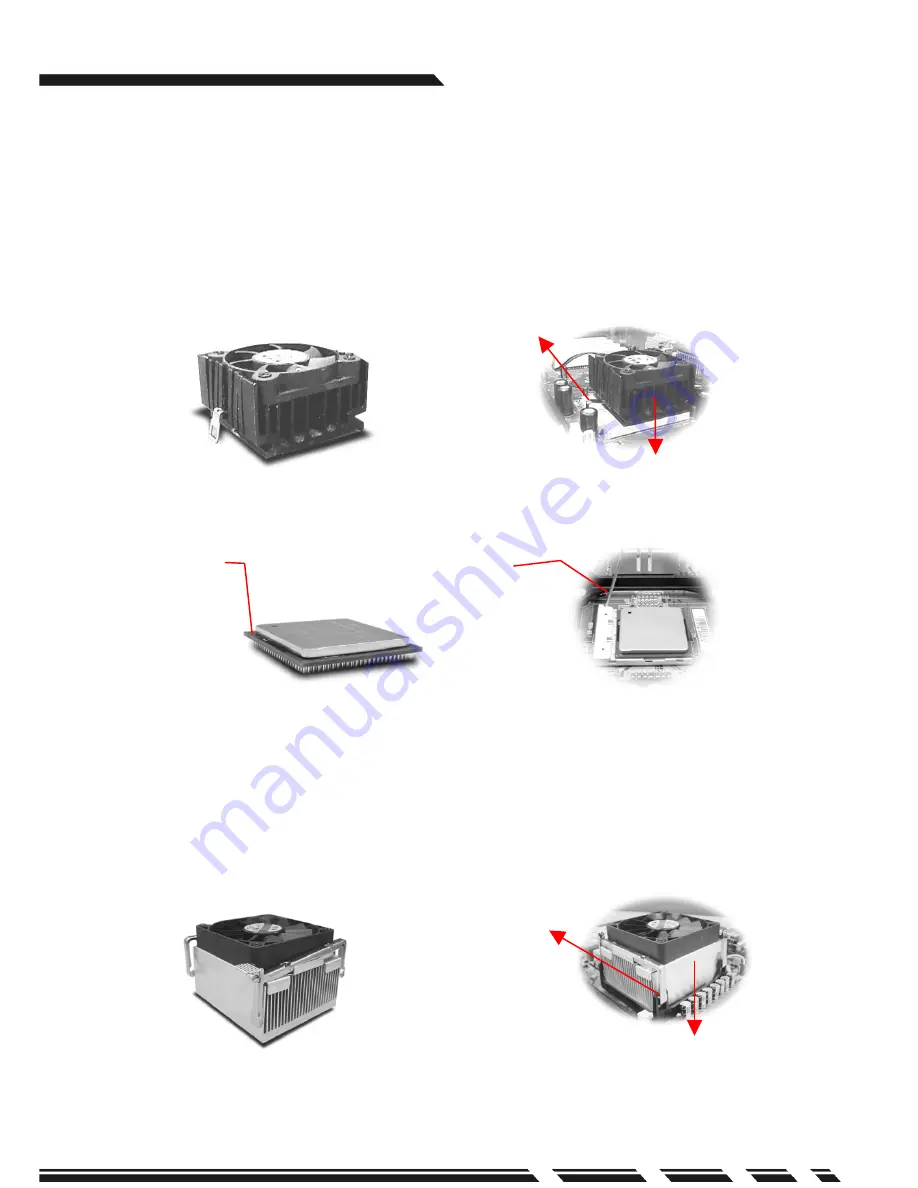
Install fan on top of CPU
Click the heat sink
locker to the
motherboard
retention module.
Lever
CPU Pin
1. Insert the CPU on the CPU socket. Before installation, lift up the lever and align the
cut of the CPU with the marking on the socket.
2. Pull down the lever to lock the CPU on the socket after installation. When you are
installing the heat sink, please make sure to keep the heat sink tight against the
CPU to obtain the best cooling result.
3. Apply the thermal compound to one side of the template, and ensure the compound
is spread evenly across the template and repeat if necessary.
4. Connect fan power connector to the CPU FAN connector on the motherboard.
Ŝ
CPU(For Intel
Pentium
4 processors)
1.Insert the CPU on the CPU socket. Before installation, lift up the lever and align the
cut of the CPU with the marking on the socket.
2.Pull down the lever to lock the CPU on the socket after installation. Put CPU cooler
on retention module and make sure to keep the heat sink tight against the CPU to
obtain the best cooling result. Lock the cooler on retention module.
3. Apply the thermal compound to one side of the template, and ensure the compound
is spread evenly across the template and repeat if necessary.
4. Connect fan power connector to the CPU FAN connector on the motherboard.
Install fan on top of CPU
Click heat sink
lock on the CPU
socket


