


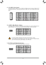
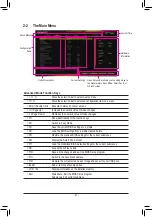
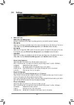

8) M2P_CPU
(Note)
/M2A_SB (M.2 Socket 3 Connectors)
The M.2 connector supports M.2 SATA SSDs or M.2 PCIe SSDs.
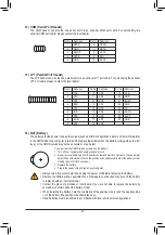
Follow the steps below to correctly install an M.2 SSD in the M.2 connector.
Step 1:
Locate the M.2 connector where you will install the M.2 SSD, use a screwdriver to unfasten the screw on
the heatsink and then remove the heatsink. (Only for B560M DS3H PLUS has the heatsink)
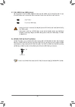
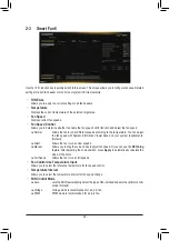
Step 2:
Locate the proper mounting hole based on the length of your M.2 SSD drive. If needed, move the standoff
to the desired mounting hole. Insert the M.2 SSD into the M.2 connector at an angle.
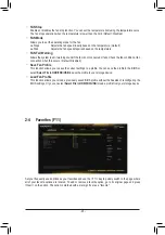
Step 3:
Press the M.2 SSD down and then use the included screw to secure it in the connector. Remove the
protective film from the bottom of the heatsink. Then replace the heatsink and secure it to the original hole.
F_USB30
F_AUDIO(H)
DB_PORT
F_PANEL(NH)
F_PANEL
(H61M-D2)
ACPI_CPT
(GA-IVB)
BIOS_PH
(GA-IVB)
SMB_CPT
(GA-IVB)
CLR_CMOS
CI
DIS_ME
GP15_CPT
(GA-IVB)
XDP_CPU
XDP_PCH
(GA-IVB)
TPM
w/housing
Voltage measurement module(X58A-OC)
PCIe power connector (SATA
)(X58A-OC)
DI
P
12
3
DIP
1 2 3
DI
P
12
3
DIP
12
3
1
1
1
1
BIOS Switcher (X58A-OC)
PWM Switch (X58A-OC)
M_SATA
PWM Switch (SW1)(X79-UD7)
DIP
1 2 3 4 5
Voltage measurement points(G1.Sniper 3)
BIOS Switcher (SW4)
GAIN
PCIe Control (Z87X-UP7)
ATX_12V_2X
3
F_USB3 (Front Panel)
SATA
_Express
SATA
_Express
SATA
_Express
PCIe/DIMM Control (Z97X-SOC Force)
M.2
MINI PCIE
THB_C
THB_C
M.2 Wi-Fi
M2_10G
Subzero
Sense
M2_10G with WIFI module
M2_WIFI
LED_IO (4-pin)
J_HDMI(NH)
OC_LED/OC_BT
M.2
MINI PCIE
U.2
SATA
_SGP
LED_C(5-pin)
SPDIF_O (4-pin)
BAT
USB20_OB
THB_C
THB_C1
F_USB31C
eDP
F_USB30/31C
VROC
TPM_new
GPIOX8
M2_32G with GC-M2-U2
SPI_TPM
PW_SW
SYS_FAN
EXT_PWR
LED_DDR
60
80
110
F_USB30
F_AUDIO(H)
DB_PORT
F_PANEL(NH)
F_PANEL
(H61M-D2)
ACPI_CPT
(GA-IVB)
BIOS_PH
(GA-IVB)
SMB_CPT
(GA-IVB)
CLR_CMOS
CI
DIS_ME
GP15_CPT
(GA-IVB)
XDP_CPU
XDP_PCH
(GA-IVB)
TPM
w/housing
Voltage measurement module(X58A-OC)
PCIe power connector (SATA)(X58A-OC)
DI
P
12
3
DIP
12
3
DI
P
12
3
DIP
1 2 3
1
1
1
1
BIOS Switcher (X58A-OC)
PWM Switch (X58A-OC)
M_SATA
PWM Switch (SW1)(X79-UD7)
DIP
1
2
3
4
5
Voltage measurement points(G1.Sniper 3)
BIOS Switcher (SW4)
GAIN
PCIe Control (Z87X-UP7)
ATX_12V_2X3
F_USB3 (Front Panel)
SATA_Express
SATA_Express
SATA_Express
PCIe/DIMM Control (Z97X-SOC Force)
M.2
MINI PCIE
THB_C
THB_C
M.2 Wi-Fi
M2_10G
Subzero
Sense
M2_10G with WIFI module
M2_WIFI
LED_IO (4-pin)
J_HDMI(NH)
OC_LED/OC_BT
M.2
MINI PCIE
U.2
SATA_SGP
LED_C(5-pin)
SPDIF_O (4-pin)
BAT
USB20_OB
THB_C
THB_C1
F_USB31C
eDP
F_USB30/31C
VROC
TPM_new
GPIOX8
M2_32G with GC-M2-U2
SPI_TPM
PW_SW
SYS_FAN
EXT_PWR
LED_DDR
80
60
M2P_CPU
(Note)
M2A_SB
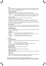
(Note) Supported by 11th Generation processors only.
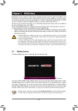
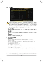
Installation Notices for the M.2 and SATA Connectors:
The availability of the SATA connectors may be affected by the type of device installed in the M.2 sockets.
The M2A_SB connector shares bandwidth with the SATA3 1 connector. Refer to the following table for details.
•
M2A_SB:
SATA3 0
SATA3 1
SATA3 2
SATA3 3
SATA3 4
SATA3 5
M.2 SATA SSD
a
r
a
a
a
a
M.2 PCIe SSD
a
a
a
a
a
a
No M.2 SSD Installed
a
a
a
a
a
a
a
: Available,
r
: Not available
Connector
Type of
M.2 SSD
•
M2P_CPU
(Note)
:
SATA3 0
SATA3 1
SATA3 2
SATA3 3
SATA3 4
SATA3 5
M.2 PCIe SSD
a
a
a
a
a
a
No M.2 SSD Installed
a
a
a
a
a
a
a
: Available,
r
: Not available
* The connector supports only PCIe SSDs.
Connector
Type of
M.2 SSD
- 15 -